
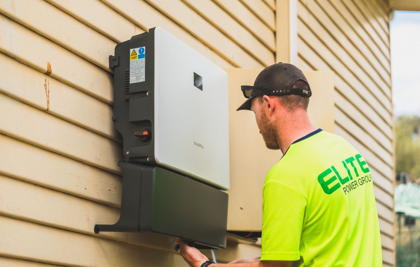
How to Minimize EMI in Solar Inverter Systems
Do not start with a random ferrite, extra ground wire, or metal shield. First record the symptom, identify the source, coupling path, and affected equipment, then compare the installed cable routes, bonding, shield terminations, accessories, and settings with the exact approved design. Correct documented deviations before selecting a manufacturer-approved suppression measure—and verify the result under the operating condition that caused the problem.
Fix the installation path before adding parts
The safest sequence is evidence first, configuration second, suppression last. It reduces false diagnoses and protects the inverter’s safety, listing, grounding, and warranty conditions.
What exactly fails, and when?
Record the affected device, error, location, time, inverter state, PV output, switching event, frequency band, and whether the concern affects safety or a regulated service.
Does the installation match the approved design?
Check the exact inverter model, firmware, cable type and route, DC input assignment, glands, shield terminations, bonding, communications accessories, and documented filters.
Which mode and path fit the evidence?
Separate conducted from radiated disturbance, and common-mode from differential-mode current. The right remedy depends on the actual path—not the symptom name alone.
Can the team repeat the condition safely?
Use an approved plan, qualified personnel, suitable instruments, and fixed acceptance criteria. If the symptom affects critical systems or radio services, involve the manufacturer and an EMC specialist.
PV DC can remain energized in daylight, and an inverter may also connect to grid AC, batteries, generators, auxiliary supplies, control circuits, and charged internal capacitors. An OFF indication, opened AC disconnect, or rapid-shutdown state does not prove that every terminal is de-energized. Do not open equipment, alter protective earthing, add filters, move shield bonds, bypass residual-current, ground-fault, arc-fault, anti-islanding, or interlock functions, or perform measurements on exposed parts unless qualified personnel isolate every source, wait the specified discharge time, verify absence of voltage, and follow the approved electrical safe-work procedure and exact equipment instructions.
Every EMI problem has a source, path, and victim
Electromagnetic interference (EMI) is unwanted electromagnetic energy that disrupts equipment. Electromagnetic compatibility (EMC) is the ability of equipment and systems to operate acceptably in their electromagnetic environment.
An inverter’s fast switching edges interact with cable inductance, capacitance, enclosure geometry, filters, and connected equipment. That can create multiple frequency components and more than one coupling path. There is no single “solar inverter noise frequency,” universal separation distance, or ferrite size.
Match the remedy to the noise mode and path
A symptom such as a network dropout does not identify the mechanism. Use the exact circuit, cable geometry, operating condition, and measurement evidence to narrow the path.
| Mechanism | What it means | Useful evidence | Correction direction—not a universal instruction |
|---|---|---|---|
| Conducted common mode | Similar high-frequency voltage or current appears on multiple conductors relative to chassis, PE, or another reference. | Correlation on several conductors; cable-to-earth capacitance; shield, gland, bonding, or enclosure discontinuity. | Restore the intended high-frequency return path. Review bonding, shield termination, cable entry, and an approved common-mode component. |
| Conducted differential mode | Disturbance exists between conductors of the same power or signal circuit. | Noise measured across the pair; switching-current loop; input/output filter behavior; operating-point dependence. | Keep the intended pair together and review the exact differential filter, reactor, capacitor, or cable arrangement specified for that circuit. |
| Capacitive coupling | A rapidly changing voltage couples through electric-field capacitance into a nearby circuit. | Long parallel exposure; small separation; sensitive high-impedance input; change after rerouting. | Use approved spacing, barriers, shielding, glands, and shorter parallel exposure. Preserve code, service access, and manufacturer requirements. |
| Inductive coupling | A changing current creates magnetic flux that links a nearby loop. | Large source or victim loop area; high-current switching event; orientation and route dependence. | Minimize unnecessary loop area and keep outgoing/return conductors together where the equipment design permits. |
| Radiated coupling | A cable or enclosure opening acts as an antenna at part of the disturbance spectrum. | Band- and distance-dependent radio or sensor symptom; cabinet-entry details; cable length and orientation. | Review enclosure continuity, cable entry, shield termination, routing, and the source current path before selecting suppression hardware. |
| Immunity weakness | The affected equipment cannot tolerate the electromagnetic environment even if the source is unchanged. | Only one receiver fails; different cable/interface works; problem appears during a defined transient or RF event. | Review the victim interface, isolation, cable category, filtering, firmware, grounding reference, and applicable immunity requirement. |
Common mode and differential mode often exist together. A component that improves one path can leave the other unchanged or shift the spectrum.
Cable geometry is usually the highest-leverage field variable
Place the inverter, DC equipment, AC distribution, communications cabinet, and sensitive loads on one drawing. Mark every power, PE, shield, auxiliary, and data path—including short jumpers and cable entries.
For Ethernet, RS-485, CAN, meters, and sensors, keep the specified twisted pairs intact and follow the exact topology, termination, biasing, isolation, shield, gland, and reference requirements. Do not publish one universal RS-485 resistor, maximum length, or shield rule. Fiber can remove one metallic data-coupling path, but its media converters and power supplies can still emit or receive disturbance.
Manufacturer instructions may specify spacing, barriers, cable type, routing zones, or gland systems for an exact product. Use those values as product requirements—not as a portable rule for a different voltage, enclosure, interface, or jurisdiction.

Three related functions—three separate questions
Protective earthing (PE) is a safety function. Equipotential or functional bonding can provide a controlled high-frequency current path. A cable shield helps control field coupling when the whole cable/interface system and its termination support that purpose. Calling all three “ground” hides important differences.
Adding a conductor, moving a shield connection, or scraping a painted surface can change fault-current paths, touch safety, corrosion, surge behavior, isolation monitoring, communications, and common-mode current. Never disconnect, lift, switch, or add series impedance to PE to cure an EMI symptom. Never assume that “single-point grounding” is the correct universal architecture for a large PV site.
Shield termination is frequency- and product-dependent. Some interfaces require a low-impedance circumferential connection through an EMC gland or clamp; other interfaces specify a different scheme. A long pigtail can behave very differently at high frequency, but that does not justify inventing a new connection. Follow the exact inverter and communications documentation.
Use filters and ferrites only after the path is known
A suppression component has frequency-dependent impedance, losses, leakage, thermal behavior, fault duties, and installation constraints. “It fits around the cable” is not a selection method. Which conductors pass through a common-mode component changes what it does; a core around one conductor is not equivalent to a core around all intended circuit conductors. Never place a series suppression component in PE.

Choke or ferrite
Can add impedance to a defined common-mode path over part of the spectrum. Check the cable, mode, frequency range, current, temperature, saturation, turns, and supported installation.
Approved line filter
May reduce a measured conducted path when approved for the inverter, voltage, phase/topology, current, grid, enclosure, leakage, protection, fault level, and operating environment.
Shielded or isolated link
Can reduce metallic coupling when the exact communications hardware supports it. Confirm protocol, power, reference, cybersecurity, diagnostics, and maintenance implications.
A surge protective device (SPD) is selected to limit transient overvoltage. It does not replace a conducted-emissions filter, shield, or cable-layout correction. A line reactor also changes circuit impedance or current behavior but is not automatically an EMC filter. Keep these roles separate and use the project’s inverter SPD guidance and surge protection coordination guide for transient protection.
| Before approval | Questions the design team must answer | Why it matters |
|---|---|---|
| Electrical fit | Which port, voltage, current, phase, conductor, frequency band, and common/differential mode are involved? | A component can be ineffective, overheated, saturated, or unsafe outside its evaluated duty. |
| Safety and protection | What are the leakage, insulation, discharge, fault-current, protective-device, PE, and touch-current implications? | EMC improvement cannot come at the cost of shock, fire, fault clearing, or listed-product conditions. |
| Physical layout | Where are the filter, input/output conductors, enclosure contact, cable entry, and bypass paths? | Routing input beside output or bypassing a controlled shield path can defeat the intended function. |
| Evidence | Is the part named by the inverter manufacturer? If third-party, is written compatibility and engineering approval available? | Product compliance and warranty can depend on the exact tested or declared configuration. |
| Verification | What before/after test, operating state, acceptance limit, and record will prove the change? | A subjective improvement may hide a shifted frequency or a new immunity problem. |
Collect evidence before changing the system
Start with non-invasive data. When measurements are needed, the instrument, probe, bandwidth, reference plane, operating state, location, and interpretation are all part of the test.
Define the symptom
Name the affected equipment, visible error, duration, location, and operational consequence. “The inverter affects the network” is not specific enough.
Time-correlate events
Compare the symptom with PV output, startup, relay operation, battery charging, grid events, communications activity, weather, and firmware changes.
Freeze the configuration
Record model, firmware, settings, cable types, routes, glands, shields, approved accessories, cabinet entries, and recent service work.
Compare with documents
Check the exact manuals, one-line, routing drawing, BOM, commissioning record, and supplier-supported cable or filter arrangement.
Form a path hypothesis
Decide which source, conducted/radiated path, common/differential mode, and victim behavior best fit the evidence.
Plan the measurement
Use qualified personnel and suitable equipment. Define operating conditions, test points, safety boundaries, bandwidth, detector, reference setup, uncertainty, acceptance criteria, and escalation.
Make one approved change
Restore a documented deviation first. If suppression is needed, obtain manufacturer or engineering approval and keep other variables stable.
Repeat and record
Recreate the same operating state, compare the same evidence, check for new symptoms, and update the as-built baseline and change record.

Use the inverter manufacturer, project engineer, utility, and a competent EMC laboratory when interference affects safety functions, emergency communications, regulated radio services, neighboring operations, medical or laboratory equipment, or a custom multi-vendor system—or when a proposed correction changes a listed configuration. A near-field probe, spectrum scan, or site comparison can help locate a problem, but it is not automatically a compliance test. A dB change is meaningful only when the setup, operating state, bandwidth, detector, probe, distance, and uncertainty remain comparable.
Turn a complaint into a testable hypothesis
The same visible symptom can have EMI and non-EMI causes. Addressing, firmware, connectors, power supplies, protocol mismatches, environmental damage, and ordinary cable faults still need to be ruled out.
Suspect a power-to-data path—but verify it
Collect link counters, inverter output/state, cable route, cable category, shield/gland condition, interface power, recent service changes, and the exact connection diagram. First restore deviations from the approved communications and routing instructions.
Map every new external conductor
Record the affected band, time, distance, antenna orientation, operating state, new inverter cabinets, feeder and data routes, bonding changes, and accessories. Because a radio service is involved, use a planned site assessment and specialist support.
Check reference, supply, and immunity paths
Time-correlate relay or converter states, then review sensor wiring, auxiliary supply, isolation, cable route, cabinet entries, grounding reference, input configuration, and supported suppression at the affected interface.
Use the before/after record
Compare cables, glands, filter part numbers, shield clamps, PE/bonding, firmware, input assignment, route photographs, and work orders. Restore an approved configuration or obtain a documented corrective design—do not guess at substitutions.
A product EMC result is not a whole-site guarantee
EMC evidence applies to a defined product, ports, cable configuration, accessories, operating modes, test setup, environment, standard edition, and market. IEC 62920:2017 with its 2021 amendment specifies EMC requirements and test methods for DC-to-AC power conversion equipment used in photovoltaic systems, including grid-interactive and stand-alone equipment within its stated scope. CISPR 11:2024 supplies radio-frequency disturbance limits and measurement methods for equipment within its own scope. Confirm the exact product standard, classification, national adoption, and edition required for the ordered inverter and market.
Generic standards such as IEC 61000-6-2 for industrial immunity and IEC 61000-6-4 for industrial emissions apply only when the equipment and environment fit their scopes and no more specific applicable product or product-family EMC standard governs. Passing an emissions test does not prove immunity; passing an immunity test does not prove emissions compliance.
In the United States, 47 CFR Part 15 is an RF-device regulatory framework, not a solar-inverter layout manual. Electrical installation safety, product listing, utility interconnection, and customer EMC requirements remain separate. In the European Union, the EMC Directive also requires fixed installations to apply documented good engineering practice and respect the intended-use information for their components. International projects must use the editions and national adoptions required by the market and authority.
Harmonics, power factor, voltage unbalance, flicker, and high-frequency conducted or radiated disturbance can interact, but they use different definitions, measurements, and limits. Define the affected equipment and frequency concern before selecting a remedy. For meter-specific symptoms, use SENTOP’s electrical panel monitoring guidance.
Build the EMI requirement into the submittal—not into a field workaround
SENTOP can review the low-voltage isolation, surge protection, circuit protection, monitoring, terminal, and distribution components around a solar panel or BOM. Inverter EMC investigation and final system engineering remain with the inverter supplier, qualified project engineer, and competent test team.
Solar inverter EMI questions answered
What is electromagnetic interference in a solar inverter system?
It is unwanted electromagnetic energy that disrupts another function or device. A solar inverter can be a source because it switches voltage and current rapidly, but a real problem depends on the coupling path, cable and enclosure geometry, connected equipment, operating state, and the victim’s immunity. EMI may be conducted on wiring or coupled through electromagnetic fields.
Can better grounding always fix solar inverter EMI?
No. Protective earthing, functional bonding, and shield termination serve different purposes. An added connection can change fault paths, common-mode current, surge behavior, corrosion, isolation monitoring, or communications. Never alter PE or add a “ground” from generic advice. Follow the approved design and exact manufacturer instructions.
Should a shield be connected at one end or both ends?
There is no universal answer. It depends on the interface, cable construction, frequency range, grounding and bonding arrangement, product design, and installation environment. Use the exact communications and inverter documentation, including the required gland or clamp. A shield without the specified termination may not perform as expected.
Will a ferrite core fix inverter radio or communication interference?
Only when the ferrite is suited to the real mode, frequency range, cable, current, temperature, turns, and installation. It may improve one common-mode path and leave another path unchanged. Diagnose first, correct documented layout or termination deviations, and use only a manufacturer-approved or engineered component with a before-and-after verification plan.
Is a surge protective device the same as an EMI filter?
No. An SPD limits transient overvoltage from events such as lightning or switching surges. An EMI filter is selected for a defined conducted disturbance path and frequency behavior. One does not replace the other. Both must be coordinated with the exact voltage, system, protection, grounding, enclosure, and applicable product instructions.
Can an inverter pass EMC testing and still cause a site problem?
Yes. Product evidence covers a defined model, ports, accessories, cables, configuration, operating modes, test setup, standard edition, and environment. A site can differ through cable routes, enclosure entries, bonding, receivers, nearby radio services, substitutions, or multi-vendor interactions. Preserve the declared configuration and verify the completed installation.
How can I tell whether a network dropout is caused by EMI?
Do not decide from the symptom alone. Check addressing, firmware, power supplies, connectors, protocol compatibility, cable damage, configuration, and environmental conditions. Evidence becomes stronger when errors repeat with a defined inverter state or switching event and when the installed cable, shielding, or routing differs from the approved design.
When should an EMC specialist be involved?
Involve specialist support when interference affects safety functions, critical communications, regulated radio services, medical or laboratory equipment, neighboring operations, or a custom multi-vendor installation; when controlled measurements are needed; or when the proposed correction changes a listed product configuration. Early support is usually cheaper than repeated unverified modifications.
Verify the exact edition, product, market, and configuration
The following sources support the technical boundaries in this guide. Manufacturer instructions are examples for their named products, not universal wiring or clearance rules.
- IEC 62920:2017+A1:2021 — EMC requirements and test methods for PV power conversion equipment within its scope.
- CISPR 11:2024 — RF disturbance limits and measurement methods for equipment within its scope.
- IEC 61000-6-2:2016 — generic EMC immunity requirements for industrial environments where applicable.
- IEC 61000-6-4:2018 — generic EMC emission requirements for industrial environments where applicable.
- 47 CFR Part 15 — current U.S. RF-device regulatory framework.
- NREL: PV Inverter Reliability Assessment — switching transitions, parasitics, and inverter reliability context.
- SMA: Requirements for Network Cables — product-specific example of cable routing and separation guidance.
- SMA: Connecting the DC Cables — product-specific DC assignment and EMC warning.
- Fronius installation documentation — example of a specified communication-cable shield and EMC gland arrangement.
- IEC 60364-7-712:2025 — installation requirements for solar PV power supply systems.
- IEC 60364-4-44:2024 — protection against voltage disturbances and electromagnetic disturbances in low-voltage installations.
- IEC 61643-31:2018 — PV DC surge protective device requirements and test methods; a separate role from continuous EMI filtering.
- EU EMC Directive 2014/30/EU — equipment and fixed-installation EMC responsibilities within its scope.
- OSHA 1910.333 — U.S. workplace electrical safe-work boundary; not an inverter EMC design standard.
