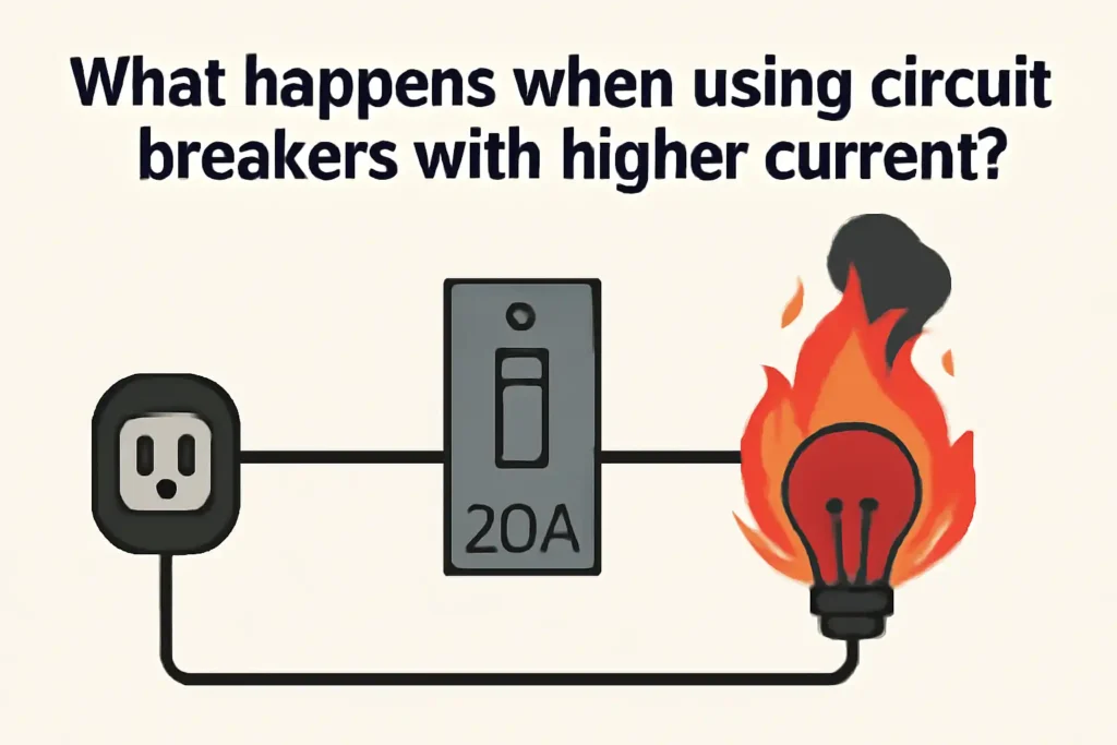
Using circuit breakers with higher current ratings might seem helpful. However, it can cause big safety problems. These breakers let more electricity flow than wires can handle. This can make wires too hot, damaging their coverings and connections. Overheating can also cause fires. Electrical problems might not be noticed, which can harm your system more. Always use circuit breakers that match your wires and devices. This keeps things safe and follows electrical rules.
Key Takeaways
- Using bigger circuit breakers can cause overheating and fires. Always match the breaker size to the wires for safety.
- Bigger breakers might miss small electrical problems. Pick the right breaker to find issues early and protect devices.
- Following the National Electrical Code (NEC) is very important. It keeps your system safe and your insurance valid.
- Talk to a licensed electrician before making changes. They make sure your system is safe and follows the rules.
- Bigger breakers can stop annoying trips during heavy power use. Make sure your system can handle the extra power safely.
Understanding Circuit Breakers with Higher Current
The role of circuit breakers in electrical systems
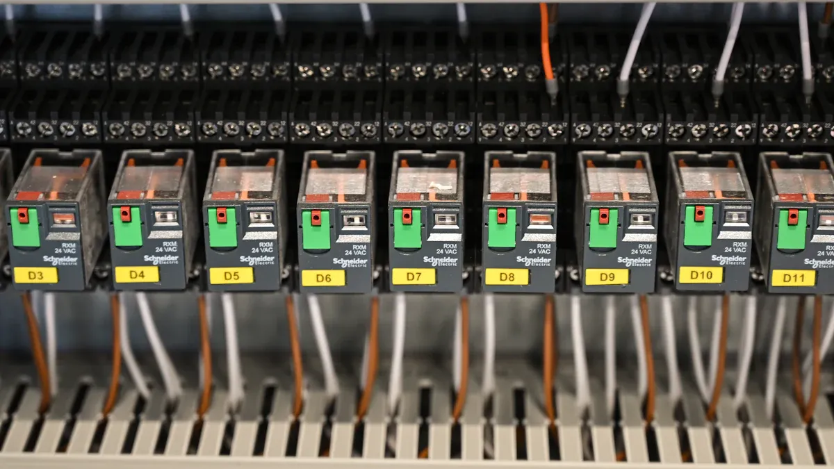
Circuit breakers protect your home’s electrical system. They watch the electricity flow and stop it if something goes wrong, like too much power or a short circuit. This helps keep your devices safe and lowers the chance of fires. For example, during a power spike, the breaker shuts off power to stop damage. Studies show circuit breakers are key for safety and preventing electrical problems.
Sometimes, circuit breakers can fail. Problems like broken parts or stuck switches can stop them from working. Picking the right type and size of breaker is very important for keeping your system safe.
How current ratings determine circuit breaker performance
A circuit breaker’s current rating shows how much power it can handle safely. Each breaker is made to stop electricity if it goes over a certain limit. If the power gets too high, the breaker shuts off to protect wires and devices. Breakers with the right rating quickly find and fix electrical issues, keeping your system safe.
For example:
- A 20-amp breaker can handle up to 20 amps of power.
- If the power goes over 20 amps, the breaker shuts off to prevent damage.
Safety tests, like UL 489, check if breakers work well under tough conditions. These tests make sure breakers can handle problems without breaking.
Why higher current ratings can pose risks
Using breakers with higher current ratings might seem smart, but it can be risky. High-rated breakers might not shut off during quick power surges when devices start. This delay lets too much power flow, which can cause overheating or fires.
Wrong breakers can trip too often or fail to protect your devices. For example:
- Breakers must act fast during overloads or short circuits.
- They should stay on during harmless power surges.
- Some breakers have delays to handle temporary power spikes safely.
Choosing the right breaker keeps your system safe and working well.
Risks of Using Circuit Breakers with Higher Current Ratings
Overheating and fire hazards in wiring
Using circuit breakers with higher current ratings can make wires too hot. When too much electricity flows, wires heat up more than they should. This heat can melt the plastic covering on wires, showing the metal inside. Bare wires can cause sparks, short circuits, or even fires.
Studies show too much current can be very dangerous. Loose wire connections can make sparks that might start fires. Uneven electricity use in wires can also cause problems, especially in older homes. In dry places, these issues might even lead to wildfires.
To stay safe, use circuit breakers that match your wires’ limits. If the breaker is too strong, it can make your home unsafe and put your family in danger.
Failure to detect and prevent electrical faults
Breakers with higher current ratings might miss electrical problems in your system. These breakers only shut off when the electricity goes over their high limit. If a problem happens below this limit, the breaker won’t stop it. This can harm your devices and damage your home’s wiring over time.
For example, a loose wire can make electricity flow the wrong way. This can ruin devices, cause shocks, or even start fires. A correctly rated breaker would shut off power to stop these dangers.
Using the right breaker helps find and fix problems quickly. This keeps your home’s electrical system safe and working well.
Non-compliance with safety codes and regulations
Using a breaker with a higher rating without checking can break safety rules. Electrical codes, like the National Electrical Code (NEC), tell you the right breaker size for wires and devices. These rules are made to protect people and homes.
Breaking these rules can cause big problems. You might face fines or lose insurance coverage. If a fire happens, your insurance might not pay if the breaker doesn’t follow the rules.
To avoid trouble, always follow NEC rules and ask an electrician for help. Following the rules keeps your home safe and legal.
Technical Consequences of Mismatched Circuit Breaker Ratings
Impact on electrical system performance and reliability
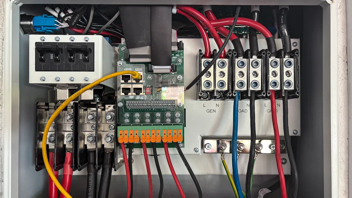
Wrong circuit breakers can upset your electrical system’s balance. If a breaker lets more power flow than wires can handle, it overloads the system. This makes wires weaker and less efficient over time. You might see flickering lights, uneven power, or devices breaking early.
High-rated breakers may ignore small electrical problems. These small issues can build up and stress your system. Over time, this can cause sudden failures and unreliable performance. Using the right breaker helps catch problems early and keeps your system working well.
Long-term damage to infrastructure and appliances
Using a breaker with too high a rating harms your home’s wiring. Wires get too hot, which ruins their protective covering. This damage spreads to outlets, switches, and other parts, costing money to fix.
Appliances also get damaged. Devices made for lower power can’t handle extra electricity. Motors in fridges, washers, and air conditioners can burn out. Electronics like computers and TVs may stop working forever. Picking the right breaker protects your home and makes appliances last longer.
Legal and insurance implications of improper installations
Installing the wrong breaker can cause legal and money problems. Courts may blame installers or makers for not following safety rules. For example:
- A hotel got sued after an employee was hurt by a bad breaker panel.
- In house fires, experts check if wiring was done right. If not, installers might be blamed instead of homeowners.
- A court case showed that a whole switchboard counts as one property unit. This changes insurance coverage when rules aren’t followed.
Breaking safety rules can lead to fines and denied insurance claims. If a fire or accident happens, insurers might not pay, leaving you to cover costs. Always use breakers that follow NEC rules to stay safe and avoid trouble.
Key Things to Know Before Using Higher Amp Circuit Breakers
Checking your wires and electrical parts
Before using higher amp breakers, check your wires and parts. Wires can only carry a certain amount of electricity safely. If you use a stronger breaker without checking, wires can overheat. This can cause fires and damage your system.
You might need an upgrade if your breaker trips often or if you add big appliances like EV chargers. To stay safe:
- Look at your electrical panel’s capacity.
- Make sure your wires can handle more electricity.
- Check if new safety devices will work with your system.
Getting a professional to check your home’s wiring helps follow rules and avoid dangers.
Making sure devices and systems can handle the upgrade
Stronger breakers affect all connected devices and systems. They let more electricity flow, which can harm devices made for less power. Motors in fridges, washers, and air conditioners can break. Electronics like computers might stop working forever.
To prevent problems, make sure your upgrade fits your devices. For example:
- Check how much power your panel can handle.
- Make sure it works for big appliances.
- Decide if your current system needs an upgrade.
Checking compatibility keeps your devices safe and your system reliable.
Asking experts for safe upgrades
Electrical upgrades need skilled help. Experts make sure your system is safe and works well. They check your wires, plan better setups, and avoid costly mistakes.
| What Experts Do | Why It Helps |
|---|---|
| Know the rules | They design safe systems that follow electrical codes. |
| Improve performance | Their plans make your system work better and waste less energy. |
| Save money | Good planning avoids errors and lowers repair costs. |
| Prevent hazards | Expert designs reduce risks like fires and short circuits. |
| Simplify permits | They ensure your upgrade meets rules, making permits easier to get. |
Hiring licensed electricians makes your upgrade safe, legal, and suited to your needs.
Following the National Electrical Code (NEC) and Local Rules
When upgrading circuit breakers, follow the NEC and local rules. These guidelines keep your home safe and legal. Ignoring them can cause accidents, fines, or insurance problems.
The NEC has important rules for electrical systems. For example:
- It tells where to install GFCI and AFCI breakers.
- It lists which wires work for different jobs.
- It limits how much power circuits can handle.
These rules stop electrical dangers and help your system work well.
Local rules often add to NEC guidelines for specific needs. Some areas need extra safety steps for weather, like humidity or heat. Following both NEC and local rules avoids trouble and keeps your system legal.
The NEC also explains how to install things correctly. Article 240 talks about overcurrent protection, like breaker types. Article 110 covers general rules, like spacing and access. NEC 110.12 says all equipment must be installed neatly. These rules prevent mistakes that could cause problems.
Tip: Always hire a licensed electrician to check your upgrades. Experts know the rules and help you avoid errors.
Following these rules protects your home and keeps your insurance valid. If your system doesn’t meet code, insurers might not pay for damages. Staying within NEC and local rules keeps your home safe and insured.
Benefits of Circuit Breakers with Higher Current Ratings
Better for handling big electrical needs
Circuit breakers with higher current ratings are made for big power use. They work well in places like factories, office buildings, and power stations. For example:
- MCCBs are great for areas needing lots of electricity.
- They handle strong power surges, keeping equipment safe from harm.
- Their strong build helps them work under heavy power loads.
If you run places like data centers or factories, these breakers give the power and safety needed for smooth work.
Fewer power interruptions in certain cases
Higher-rated breakers stop power from cutting off too often. Regular breakers might trip when motors start or appliances use extra power. This can mess up work and harm delicate devices.
Using a higher-rated breaker stops these small interruptions. It lets your system handle quick power spikes without shutting off. For example, in factories, special breakers only trip during real problems, keeping things running and protecting machines.
When higher-rated breakers are needed
You don’t always need higher-rated breakers, but they help in some cases. For example:
- In factories, they lower energy from arcs, keeping workers safer.
- They stop big problems during short circuits, avoiding major damage.
- They work well in systems needing strong fault protection, like big plants.
These breakers keep complex systems safe and steady. But always check your system’s needs before upgrading to avoid problems.
Using circuit breakers with higher current ratings can be risky. Problems like overheating, electrical faults, and breaking safety rules may happen. Using the right circuit breakers keeps your system safe. They stop overloads, short circuits, and arc faults, protecting your home or business.
Before switching to a stronger breaker, check your wires and devices. Make sure they can handle more electricity. Always follow safety rules and ask an electrician for help. This keeps your setup safe and avoids costly errors.
Tip: Choosing the right circuit breakers helps protect your system. It also makes your appliances last longer by stopping electrical damage.
FAQ
Why should you avoid using a higher-rated circuit breaker without checking your wiring?
Using a stronger breaker without checking wires can be dangerous. Wires might not handle more electricity, causing them to overheat. This can lead to fires. Always make sure your wires match the breaker’s strength to stay safe.
Why is it important to follow the National Electrical Code (NEC)?
Following the NEC keeps your electrical work safe. It stops accidents and legal trouble. If you follow the NEC, your insurance stays valid. This protects you from losing money if something goes wrong.
Why consult a professional before upgrading your circuit breaker?
Talking to an expert makes sure your upgrade is safe. They check if your system can handle the change. Experts help you follow safety rules, stopping electrical problems and dangers.
Why do higher-rated circuit breakers reduce nuisance tripping?
Stronger breakers handle quick power jumps better. This means they trip less often. This is good for places with big machines, keeping them running. But make sure your system can handle the extra power safely.
Why might higher-rated breakers be necessary in industrial settings?
Factories need stronger breakers because they use lots of power. These breakers give the right power and safety for big machines. Always check what you need before picking a breaker.
The following information may be of interest to you
Can I replace a 15 amp breaker with a 20 amp?
How to Accurately Calculate Electricity Load for Your Household
How to choose the appropriate size of circuit breaker
Can you put two lighting circuits on one circuit breaker