
10–30 A
10, 15, 20, 25, 30 A
Common small branch or equipment ratings, depending on system, conductor, load and rules.
Common does not mean interchangeable across panels or markets.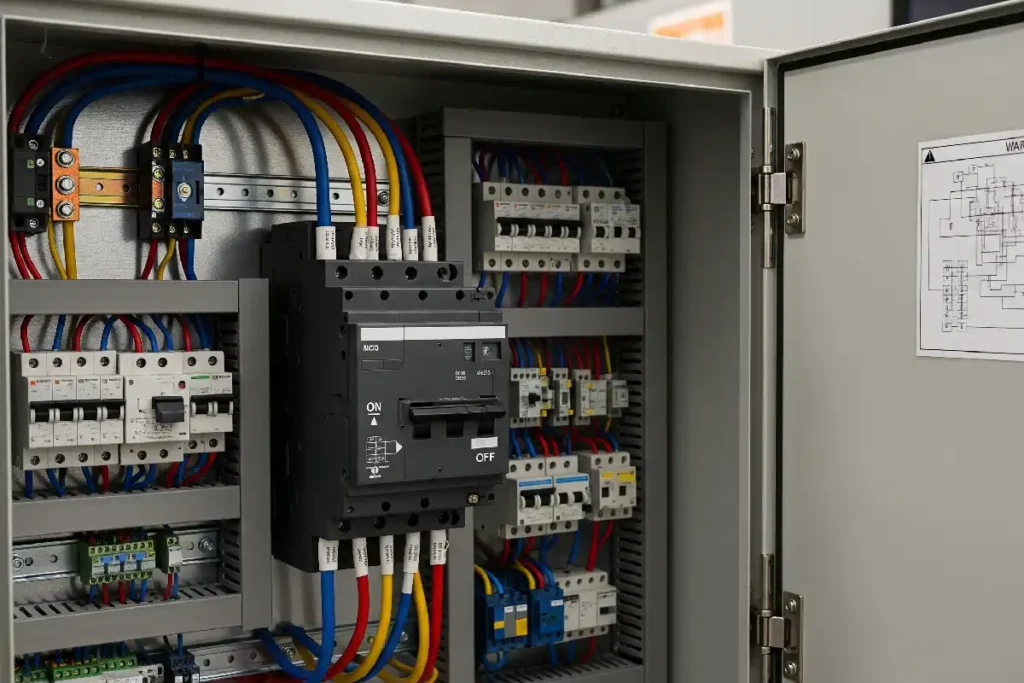
The ampere number is only one part of breaker size. Buyers and maintenance teams must also match the frame, poles, voltage, trip behavior, breaking capacity and physical connection.
A homeowner often means the handle ampere number. A panel builder may mean DIN-module width. A switchgear buyer may mean frame size. An engineer may mean interruption duty. These answers cannot be substituted for one another.
The ampere designation or configured long-time rating under stated product conditions.
The maximum current family or construction envelope, not always the installed trip rating.
The conductor arrangement and electrical system the device is designed to open safely.
Width, height, depth, mounting, bus connection, terminals and accessory clearance.
How the breaker responds, which fault duty it can interrupt and what protective function it is approved to perform.
Each field answers a separate selection question. A correct replacement must satisfy them together.
| What people call size | What it means | Why it changes the decision |
|---|---|---|
| Ampere rating | Rated current, fixed trip value or configured long-time current. | Must coordinate with the design load, conductor, terminals and applicable installation rules. |
| Frame size | Largest current rating available for a breaker construction or family. | A 250 AF construction may use a lower sensor, rating plug or trip setting, depending on the exact design. |
| Pole count | One, two, three or four mechanically linked breaker elements. | Must match the supply topology, protected conductors and required simultaneous opening. |
| Physical size | Width, height, depth, mounting, bus connection and terminal geometry. | Determines whether the device integrates with the enclosure, busbar and conductor arrangement. |
| Trip characteristic | Thermal, magnetic or electronic response versus current and time. | Changes inrush tolerance, overload response, fault clearing and coordination. |
| Breaking capacity | Fault current the breaker can interrupt under a stated standard, voltage and test condition. | Must be adequate for prospective short-circuit current at the installation point. |
| Voltage and category | AC/DC voltage plus the standard or protective function under which the device is evaluated. | A current-correct device can still be unsuitable for the system voltage or the required branch-circuit role. |
For 2023 NEC-based work, Table 240.6(A) includes 10 A as a standard inverse-time breaker rating. The complete series continues through large distribution values. Local adoption and the exact product family still control.
10, 15, 20, 25, 30 A
Common small branch or equipment ratings, depending on system, conductor, load and rules.
Common does not mean interchangeable across panels or markets.35, 40, 45, 50, 60, 70, 80, 90, 100, 110, 125 A
Larger branch, equipment and feeder directions in multiple breaker forms.
The same current can appear in MCB, panel-breaker or MCCB families.150, 175, 200, 225, 250, 300, 350, 400, 450, 500, 600, 700, 800 A
Commercial and industrial distribution where frame and trip-unit details become central.
Ask whether the number is frame, sensor, rated current or setting.1,000, 1,200, 1,600, 2,000, 2,500, 3,000, 4,000, 5,000, 6,000 A
Engineered power-distribution and switchgear applications.
Protection studies, fault duty, coordination and switchgear integration are required.Nonstandard ratings may also be permitted in defined contexts. Availability varies by breaker family, voltage, poles, trip design, breaking capacity, panel system and target-market approval.
Current ranges overlap, but construction, mounting, adjustment, interruption duty and procurement data are different.
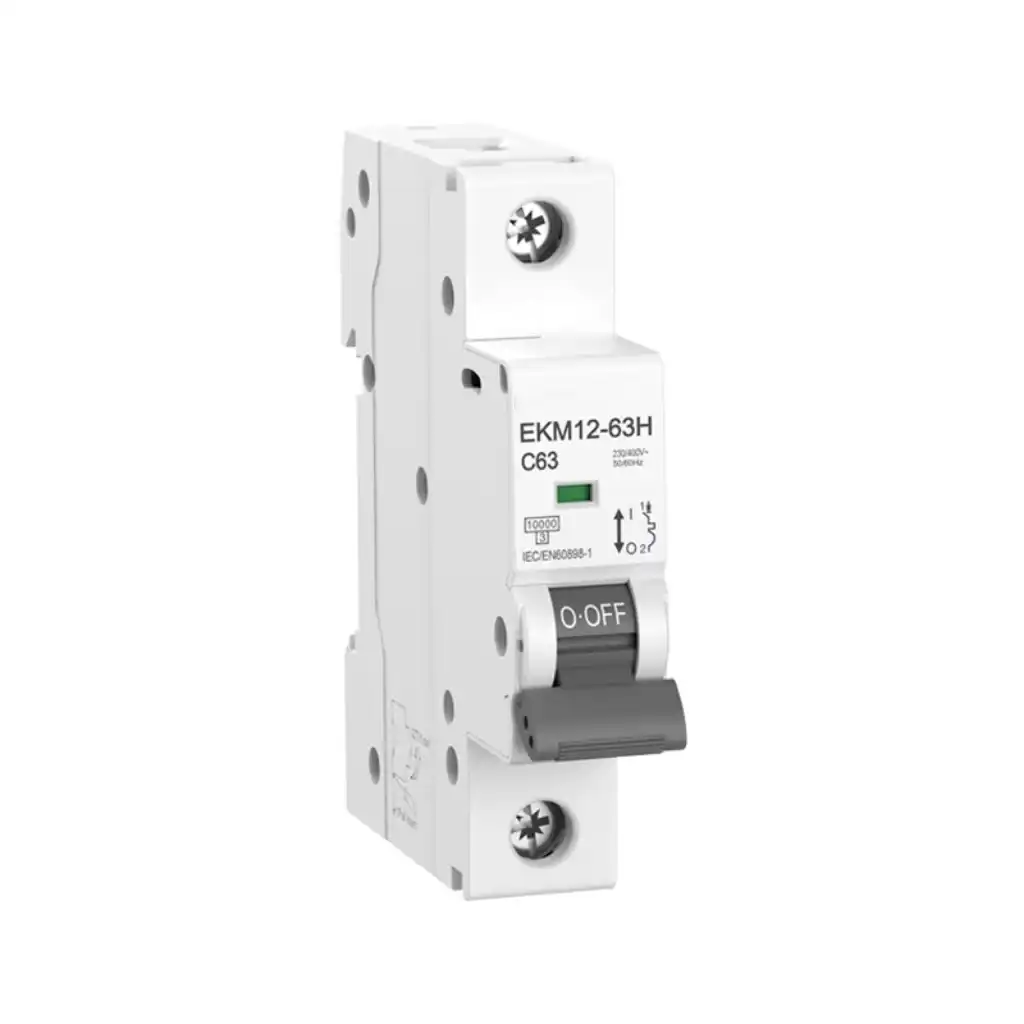
Compact DIN-rail or market-specific panel protection for final distribution and equipment circuits.
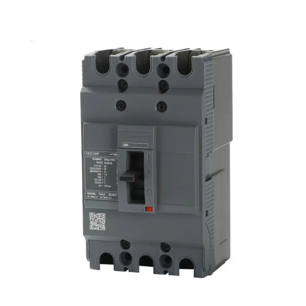
Feeder, equipment and distribution protection with larger frames and fixed or adjustable trip systems.
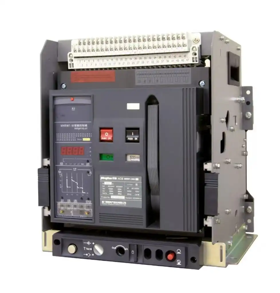
High-current switchboard protection where the complete breaker, cradle, trip unit and accessory configuration matters.
UL defines frame size as the largest ampere rating available for a group of similar molded-case construction. On applicable electronic-trip products, a sensor, rating plug and long-time setting can create a lower usable current rating. The exact relationship is manufacturer-specific.
Conceptual relationship only. It is not a universal ratio and does not represent a SENTOP model. Use the exact trip-unit documentation and approved setting range.
Poles and voltage define the system connection. The trip curve defines response. Breaking capacity defines which fault duty the breaker can interrupt under stated conditions.
This tool does not calculate or approve a breaker rating. It shows which information must be collected before a supplier, panel builder or qualified electrical professional can review the requirement.
Select the closest situation, then generate a checklist. The result stays on this page and does not submit any data.
The order matters. Starting from a product photograph or handle number skips the information that determines protection.
Branch, feeder, main, motor, control, equipment internal, PV/battery or supplementary protection.
AC/DC, frequency, voltages, grounding arrangement, source and required pole/neutral treatment.
Use the applicable code and equipment instructions. Separate continuous duty and inrush where relevant.
Material, cross-section, installation method, ambient conditions, bundling, terminals and temperature limits.
Obtain prospective short-circuit current at the breaker location and the coordination requirement.
Trip curve or electronic settings plus required residual-current, arc-fault, motor or DC function.
Panel family, mounting, bus, terminals, dimensions, accessories, enclosure and target-market approval.
Document the full catalog number, ratings, settings, approved sample, labels and order configuration.
UL states that field-added breakers must be identified as suitable for the panelboard. Different manufacturers or styles are not identical in all details and may not be interchangeable.
“Three pole, 100 A” is not enough. A useful RFQ identifies electrical duty, physical integration and evidence required for the destination market.
These verified SENTOP pages cover the product families and comparisons most closely connected to breaker sizing.
In many U.S. building panels, 15 A and 20 A are common branch ratings, while 30 A, 40 A, 50 A and 60 A are often used for equipment or larger circuits. The current NEC standard series also includes 10, 25, 35, 45, 70, 80, 90, 100, 110, 125 A and many larger values through 6,000 A. Availability and suitability depend on the exact breaker family and application.
No. Standards define product scopes, tests and ratings, but U.S. panel breakers, IEC/DIN MCBs, MCCBs and power breakers use different physical formats, voltage systems, trip technologies and approvals. Always check the applicable standard, manufacturer drawing and panel or enclosure compatibility.
Frame size normally identifies the largest ampere rating available in a group of similar breaker construction. It is not always the actual continuous-current or long-time trip setting. Applicable electronic-trip breakers may also use a sensor, rating plug and adjustable setting. Read the complete label and trip-unit documentation.
No. A 20 A device can be a plug-in panel breaker, bolt-on breaker, DIN-rail MCB, compact MCCB or supplementary protector. Width, depth, bus connection, pole count, terminals and approved panel use vary. Match the complete model and panel label, not just 20 A.
Not as a simple upgrade. The conductor, terminals, circuit load, panelboard and applicable electrical rules must support the 20 A overcurrent device. Increasing the breaker to stop trips can leave a conductor underprotected or conceal a fault. Have the circuit evaluated by a qualified professional.
They are commonly used IEC/EN 60898-1 instantaneous-trip characteristic categories: B is 3–5 times rated current, C is 5–10 times and D is 10–20 times. They are not physical sizes or quality grades. Selection must consider load inrush, conductor protection, available fault current and required disconnection time.
No. The kA or interrupting rating describes fault interruption under stated conditions. It does not set conductor ampacity, normal load current, pole count, trip curve or panel compatibility. It is one required selection field alongside the ampere rating.
No. Physical fit does not prove approved bus engagement or panelboard suitability. Follow the panelboard marking and manufacturer documentation. Only use a classified replacement where the exact breaker and panel combination is specifically covered.
These sources support the rating, scope and compatibility framework. The locally adopted code, exact product data and qualified project review take priority for installation.
Include the circuit function, system voltage, current, poles, load and inrush, conductor, available fault current, panel model, mounting, required standard, quantity and full replacement reference.