

Types of RCCBs: AC, A, F, B and How to Choose
The useful answer is not one list. First choose the device function—RCCB or RCBO. Then choose the residual-current waveform class: AC, A, F or B. After that, verify sensitivity, load current, time behavior, poles, neutral treatment, fault coordination, environment and exact certification. These labels solve different parts of the specification.
There are four main waveform classes—but at least six decisions
Type AC, A, F and B describe the residual-current forms a device is designed to detect. They do not tell you whether the product includes overload protection, what normal current it can carry, how quickly it trips, how many poles it has, or whether it fits your equipment standard.
A verified simple AC load may allow Type AC where local rules permit it. Loads with rectifiers often point toward Type A. Certain single-phase inverter loads may require Type F. Equipment capable of smooth DC residual current may require Type B or another specifically approved protection architecture. The equipment maker and adopted installation rules must confirm the result.
RCD is the umbrella; RCCB and RCBO are not interchangeable
Procurement errors often start before the waveform class is discussed. A document that asks only for an “RCD breaker” may leave the supplier guessing whether overcurrent protection belongs inside the same device.
RCD
Residual current device is the broad family name for equipment that responds to residual current. It does not identify one construction or prove that overcurrent protection is included.
Use the exact product category in the BOM.RCCB
A residual current operated circuit-breaker without integral overcurrent protection. It needs coordinated overload and short-circuit protection elsewhere in the design.
IEC 61008-1 covers household and similar RCCBs within its stated scope.RCBO
A residual current operated circuit-breaker with integral overcurrent protection. Its residual-current type and its overcurrent characteristics both need specification.
IEC 61009-1 covers household and similar RCBOs within its stated scope.MCB, RCM and GFCI
An MCB provides overcurrent protection, not residual-current protection. An RCM may monitor and alarm without opening the circuit. North American GFCI is a separate product and code ecosystem.
Do not translate these labels as direct one-for-one substitutes.For a practical product split, compare SENTOP's RCCB product range, the broader RCD and RCBO range, and MCB options. Newer readers can also use the electrical glossary. A product page is a starting point. The exact ordering code, datasheet and certification record control.
The device watches the current balance, not a single conductor
All live conductors assigned to the protected circuit pass through the device's sensing system as the product diagram requires. In normal operation, outgoing and returning current balance. A current path outside that intended set creates residual current, and the device may open when its tested operating conditions are met.
Type AC, A, F and B: what each class adds
Think of these as tested response envelopes, not quality grades. A broader envelope can be necessary for a particular electronic load, but it does not automatically make the device the best fit for every circuit.
Sinusoidal AC residual current
Type AC is intended for residual sinusoidal alternating current at the rated frequency. It can fit verified simple loads where the adopted rules permit it.
Do not assume a modern electronic appliance produces only this waveform. Confirm the load or equipment instruction.AC plus pulsating DC
Type A adds response to pulsating direct residual current. It is widely relevant to single-phase electronic loads that use rectifiers.
Type A is not designed as universal protection for smooth DC residual current or every variable-speed drive.Selected inverter-produced composites
Type F builds on Type A for certain composite residual currents that can occur when a frequency inverter is supplied phase-to-neutral or phase-to-earthed midpoint.
It is not a blanket “electronics type” or a substitute for reviewing the exact inverter topology.Includes smooth DC capability
Under IEC 62423, Type B adds response to smooth direct residual current and sinusoidal residual currents up to 1 kHz, alongside the Type A/F-related conditions in that standard.
It still needs the correct IΔn, poles, ratings, environment, system standard and product evidence.Use load evidence to narrow the class—then verify the exact device
The examples below are decision prompts, not universal prescriptions. An equipment manual, applicable installation rule or engineering study can require a different solution.
| Waveform class | Core capability | Where it may enter the discussion | What not to infer |
|---|---|---|---|
| TYPE AC | Sinusoidal alternating residual current at rated frequency. | Simple, documented AC loads where local requirements still permit this type. | That all apparently simple appliances remain free of electronic controls or DC components. |
| TYPE A | Type AC capability plus pulsating direct residual current. | Many single-phase loads with rectifier input, control electronics or switched power supplies. | That it covers smooth DC or every power-conversion topology. |
| TYPE F | Type A-related capability plus specified composite residual currents for certain single-phase inverter applications. | Selected variable-speed appliances, pumps or heat-pump equipment when the product maker calls for it. | That “frequency drive” always means Type F, especially for three-phase converters. |
| TYPE B | Includes smooth DC and higher-frequency AC residual-current capability within IEC 62423. | Some three-phase drives, PV or battery converters, UPS systems, EV charging and industrial power electronics. | That Type B is always required, always sufficient, or automatically coordinated with the equipment. |
Do not select from a marketing icon alone. Ask for the waveform classification, product standard, rated voltage/frequency, IΔn, load current In, time behavior, poles, supply conditions, short-circuit coordination and exact certificate for the ordering code.
Type S, B+, high-immunity and EV labels do not form one ladder
A product name can combine a waveform class, timing characteristic and manufacturer feature. Read each marking against the declared standard and datasheet instead of assuming every extra letter means broader waveform protection.
Selective Type S
Type S is intentionally time-delayed for upstream/downstream selectivity. It is not a waveform class and is not automatically suitable where fast additional protection is required.
Verify the complete pair with the maker's curves or coordination tables.Type B+
B+ is not another basic IEC 62423 waveform class. It is used mainly in German regional standards with a defined extended high-frequency tripping characteristic.
Use it only when the jurisdiction and exact product evidence call for it.SI, HI, APR and similar
These manufacturer labels can describe enhanced immunity to specified transient disturbances. They do not replace AC, A, F or B classification.
Ask which tests, waveforms and installation conditions the label covers.EV and RDC-DD labels
An EV-specific product or 6 mA DC-detection function belongs to a complete charging protection architecture. It is not a universal RCCB waveform class.
Match the EVSE manual, local rules and exact upstream protection arrangement.About Type G: the same letter can be used differently. In some Austrian or manufacturer documentation it describes a short-time-delay characteristic; in IEC terminology “general” can also be shortened to G. Treat the meaning as regional and product-specific. Do not confuse it with AC/A/F/B waveform capability.
IΔn, In, timing and poles answer different questions
A correct waveform class can still be the wrong device. The rated residual operating current, normal load current, operating-time characteristic, fault coordination and system interface must all fit the same design.
| Marking or property | What it means | What it does not mean | Evidence to request |
|---|---|---|---|
| IΔn | Rated residual operating current—the device's declared residual-current sensitivity under stated conditions. | Normal load-current capacity, breaking capacity, or a universal “safe” value for every protective objective. | Required protection purpose, adopted rule, trip-time data and coordination study. |
| In | Rated current the product can carry under its declared conditions. | An overload or short-circuit trip setting on an RCCB. | Load calculation, ambient/derating data, terminal range and associated OCPD. |
| GENERAL | Non-time-delayed operation with no intentional selective delay. | Zero operating time or immunity to every transient. | Applicable product-standard time envelope and exact datasheet. |
| TYPE S | Selective, intentionally time-delayed operation for an engineered upstream position. | A waveform type, nuisance-trip remedy, or universal additional-protection device. | Upstream/downstream coordination curves and the local protective rule. |
| 2P / 4P | Product pole arrangement for a documented system connection. | Residual-current waveform capability, sensitivity or permission for any single-/three-phase circuit. | One-line diagram, neutral and earthing design, product connection diagram. |
| Conditional fault data | The RCCB's declared short-circuit performance when used with the specified backup protective device. | Integral overcurrent protection or an assembly rating without coordination. | Exact backup fuse/MCB/MCCB table, assembly rating and available fault current. |
Do not raise an adjustable IΔn setting, add delay, or substitute a less sensitive device merely to stop unexplained tripping. Adjustable sensitivity and delay are more typical of industrial CBR, MRCD and residual-current relay arrangements under IEC 60947-2. Their settings require an engineered, documented and access-controlled design.
Pole arrangement, neutral treatment and supply dependence are separate checks
Two-pole and four-pole RCCBs are common formats, but “2P for every single-phase circuit” and “4P for every three-phase circuit” are not universal rules. Match the device to the actual live conductors, voltage, frequency, neutral design, earthing system, power-flow direction and declared supply conditions.
- Follow the exact diagram: every conductor that the product is designed to monitor must pass through the measuring system as shown.
- Keep PE separate: the protective conductor is not used as a normal monitored return path.
- Avoid neutral shortcuts: a bypassed or shared neutral outside the approved design can create unsafe operation or unwanted trips.
- Check supply-dependent behavior: do not assume what happens after loss of voltage or neutral; use the declared class and product documentation.
- Record the architecture: the one-line diagram and load/source arrangement must agree with the ordered poles and terminals.
Supply-condition behavior is a separate certified characteristic. Verify the exact 2024 IEC 61008/61009 classification, markings and product data, including behavior on loss of supply or neutral; do not infer it from waveform type.

The load tells you what to investigate—not the final catalog number
Power electronics can change the residual-current waveform, standing leakage and transient behavior. Use the equipment manual and actual topology to turn each application into a specification question.
Heater or basic resistive equipment
First confirm that the load truly contains no electronic controls or DC-producing elements and that Type AC is allowed by the adopted rules.
Do not judge from the product's everyday name alone.Appliances, IT and control power
Single-phase rectifier inputs can produce pulsating DC residual current, bringing Type A into the discussion.
Check cumulative leakage and the complete circuit, not one load in isolation.Heat pump, pump or variable-speed appliance
Certain phase-to-neutral inverter loads can create composite residual currents addressed by Type F.
Follow the appliance maker's specified RCD type and installation conditions.Three-phase VFD, UPS or converter
Smooth DC and higher-frequency components may require Type B or a different industrial residual-current protection architecture.
Review topology, leakage, switching frequency, filters and the equipment standard.PV and battery conversion
Some inverter designs can contribute DC residual current; others include monitored functions that affect the required external arrangement.
Use the exact inverter manual, local rules and approved system documentation.EVSE and DC detection
A charging point may use Type B, or an expressly permitted Type A/F plus an IEC 62955 RDC-DD architecture.
“EV charger” does not prove one universal RCD type. Treat EVSE, RCD and RDC-DD as one system.For adjacent design context, see SENTOP's automation and machine-control applications and solar and energy-system solutions. These application pages do not replace the equipment-specific protection study.
Why “Type B for every charger” is too simple
IEC 62955 covers residual direct-current detecting devices used with permanently connected AC Mode 3 charging equipment. That RDC-DD is a separate function inside a larger protection arrangement; it is not a new AC/A/F/B class.
Type B architecture
The EVSE or local installation rule may require a Type B RCD to address smooth DC residual current.
Verify poles, IΔn, load current, timing, fault duty and exact certificate as well.Type A/F plus RDC-DD
The equipment instructions and adopted rule may explicitly allow a stated Type A or F device with the specified 6 mA DC-detection architecture.
The RDC-DD claim does not automatically remove the upstream RCD or make any model acceptable.One approved system
Record EVSE model, supply, phase/neutral arrangement, integrated detection, upstream protective device, local code and manufacturer's schematic.
If these inputs are missing, stop at the RFQ stage rather than guessing a type.Nine steps from protection objective to approved order code
The workflow is designed for panel builders, equipment OEMs, consultants and technical buyers. It is a design and procurement process—not an installation guide.
Define the objective
State whether the RCD supports fault protection, additional protection, fire-risk reduction, continuity or another adopted requirement.
Cite the local rule and project standard.Choose the family
Decide between RCCB, RCBO, industrial CBR/MRCD, RCM or another approved function.
If RCCB is chosen, design the associated OCPD at the same time.Characterize the load
Collect manuals for drives, heat pumps, UPS, PV/battery inverters, chargers and filters. Record declared residual-current behavior.
Include normal leakage and integrated DC detection.Select waveform class
Match AC, A, F or B to the documented waveform and adopted rule.
Treat B+ and manufacturer labels as regional or product-specific extensions.Set sensitivity and timing
Select IΔn and general/selective behavior independently from the waveform class.
Do not add delay or raise IΔn to hide a problem.Prove selectivity
Review standing leakage, transients and upstream/downstream operating curves.
Use declared coordination tables for the exact devices.Match the system
Confirm voltage, frequency, poles, neutral, earthing, supply-dependence class, connection diagram and allowed power flow.
Freeze the one-line before ordering.Verify current and fault duty
Check In, ambient derating, terminals, conditional short-circuit rating, backup OCPD and assembly rating.
Use available fault-current and coordination data.Record the exact catalog number, settings where applicable, curves, certificates, load restrictions, commissioning results, test instructions and maintenance responsibility. Reassess the design whenever a converter, charger, inverter, source, earthing arrangement or downstream load group changes. SENTOP's protection selection guide provides the broader component-selection path.

In is not an overload trip setting
An RCCB's rated current In tells you what it can carry under declared conditions. It does not mean the device trips on overload at that value. Overload and short-circuit protection must come from the coordinated fuse, MCB, MCCB or other protective arrangement specified by the manufacturer and project design.
- Compare load and conductor duty: In, ambient temperature, grouping, enclosure conditions, terminals and conductor material/size must fit.
- Use the maker's backup table: identify the permitted upstream or associated short-circuit protective device and its limits.
- Check available fault current: match conditional short-circuit performance and the complete assembly rating.
- Keep standards separate: an IEC conditional rating and a North American assembly SCCR are not interchangeable labels.
- Use RCBO when appropriate: integral overcurrent protection can simplify architecture, but breaking capacity and coordination still require verification.
For a focused beginner comparison, read RCCB vs RCBO. For project fields such as voltage, current, IΔn and poles, use the custom RCCB parameter guide.
Keep the maintenance boundary clear
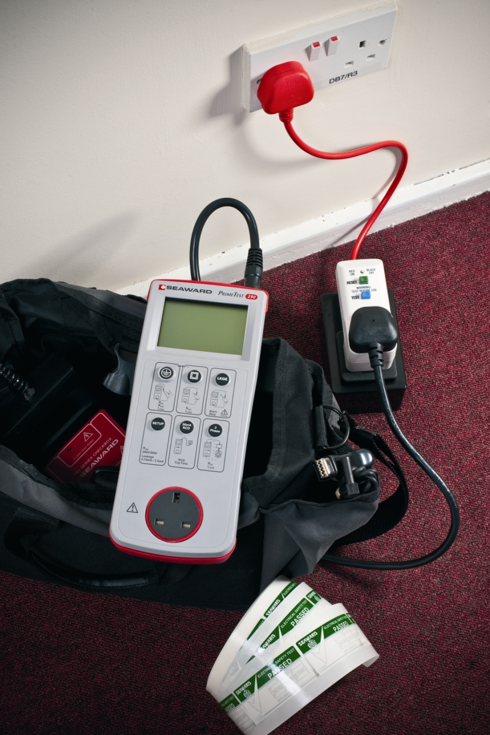
The built-in TEST mechanism provides a limited product-function check under the manufacturer's stated conditions. It does not prove the earthing system, every downstream connection, full waveform response, selectivity or complete installation safety.
- Follow the exact manual: test frequency, supply state, control sequence and expected indication can be product-specific.
- Do not open the enclosure from a generic guide: installation, electrical measurements and internal diagnosis belong to qualified personnel.
- Treat repeated trips as information: stop bypassing or repeated resetting and investigate leakage, load compatibility, wiring and device condition.
- Do not “solve” trips by reducing protection: never raise IΔn, add delay or fit a less sensitive type without a documented redesign.
- Record the result: model, circuit, load state, indication, date, exception and responsible action should be traceable.
An RCD may form part of fault protection and, where the rules require it, additional protection. It does not replace basic protection, protective earthing and bonding, overcurrent protection, isolation, lockout/tagout or safe work practices.
Eight shortcuts that create the wrong protection design
Each shortcut collapses two or more independent selection axes into one. Replace it with an evidence request.
| Shortcut | Why it fails | Better question |
|---|---|---|
| “RCBO is an RCCB type” | It confuses product function with residual-current waveform class. | Do we need residual-only protection or integral overcurrent protection? |
| “Type B is always safest” | A broader waveform envelope does not decide sensitivity, selectivity, unwanted tripping, poles or system approval. | Which residual-current waveforms can the exact load produce, and what does its manual require? |
| “30 mA is the right type” | 30 mA is an IΔn value, not a waveform class, and is not universal for every protective objective. | Which IΔn and time characteristic does the adopted rule require here? |
| “Type S detects another waveform” | S describes selective time delay, not AC/A/F/B detection capability. | Which upstream/downstream pair has documented selectivity? |
| “In provides overload protection” | On an RCCB, In is carrying capacity, not an integral overcurrent trip. | Which associated OCPD and conditional short-circuit combination is declared? |
| “4P means Type B” | Pole arrangement and waveform class are independent. | What poles, neutral treatment and waveform capability does the one-line require? |
| “6 mA detection removes the RCD” | An RDC-DD is one part of an EV charging protection architecture. | What complete arrangement do the EVSE manual and local rules approve? |
| “A logo proves the family” | Approval scope, ratings and conditions belong to an exact model and record. | Can the supplier provide the current certificate, data sheet and conditions for the order code? |
For a deeper look at the sensitivity axis, see 30 mA vs 100 mA vs 300 mA RCCBs. For foundational current terminology, the upgraded AC vs DC guide helps readers separate current form from protective-device construction.
A standard scope is not a product rating or installation approval
Use standards to define the product category and test framework. Then verify the exact model, certificate, ratings, declared conditions and end-product installation requirements.
IEC 60755:2017
General safety requirements for residual current operated protective devices. It provides minimum requirements for standards writers; it is not an order-code datasheet.
Use the specific product standard as well.IEC 61008-1:2024
Household and similar RCCBs without integral overcurrent protection, for the standard's stated scope up to 440 V AC and 125 A.
Do not extend its scope to every industrial residual-current system.IEC 61009-1:2024
Household and similar RCBOs with integral overcurrent protection, within scope up to 440 V AC, 125 A and 25 kA short-circuit capacity.
Breaking capacity and circuit coordination remain model-specific.IEC 62423:2009
Additional requirements and tests for Type F and Type B RCCBs and RCBOs, used with IEC 61008-1 or IEC 61009-1.
Do not mislabel it as a 2024 edition.IEC 60947-2:2024
Industrial circuit-breaker framework that includes CBR and MRCD architectures for instructed or skilled operation.
Adjustable settings need engineered control.UL 943 GFCI
Class A GFCI products use a different standard, system and code context. A circuit-breaker GFCI is also evaluated to its circuit-breaker standard.
Do not transfer IEC names, values or permissions by translation alone.Send the system data—not only “Type B, 30 mA”
A precise RFQ lets the supplier match product category, waveform class, ratings, coordination and evidence without guessing. SENTOP supports equipment manufacturers and OEM/ODM projects with candidate model review. Final approval remains with the responsible designer and applicable rules.
RCCB type questions, answered carefully
Short answers are useful only when their boundary stays visible. The exact product, equipment instructions and adopted rules still control the final design.
What is the difference between an RCD and an RCCB?
RCD is the umbrella term for residual-current devices. An RCCB is one type of RCD that switches on residual current but does not include integral overload and short-circuit protection. It therefore needs a coordinated overcurrent protective device.
What is the difference between an RCCB and an RCBO?
An RCCB provides residual-current protection without integral overcurrent protection. An RCBO combines residual-current and overcurrent protection in one product. Both still need the correct waveform class, ratings, poles, environment and certification.
What is the difference between Type AC and Type A RCCBs?
Type AC is designed for sinusoidal AC residual current. Type A also responds to specified pulsating DC residual current. Modern electronic loads often make Type A relevant, but the equipment manual and local rules must confirm the choice.
When should Type F or Type B be considered?
Type F is intended for certain composite residual currents from specified single-phase frequency-converter applications. Type B adds smooth DC and higher-frequency AC capability within IEC 62423. Consider either only from documented load behavior and applicable requirements—not from an appliance category alone.
Is Type B always better than Type A?
No. Type B has a broader waveform capability, but it does not automatically provide the correct sensitivity, selectivity, current rating, poles, fault coordination or immunity for every circuit. The correct device is the one whose complete specification fits the application.
Is Type S another residual-current waveform class?
No. Type S describes an intentionally time-delayed, selective characteristic. A Type S product still has a separate AC, A, F or B waveform capability. Selectivity must be verified for the exact upstream and downstream devices.
Does a 30 mA RCCB suit every circuit?
No. 30 mA is an IΔn sensitivity value, not a waveform type or universal solution. The required sensitivity and operating time depend on the protection objective, local rules, leakage, selectivity and equipment design.
Does an RCCB protect against overload and short circuit?
No. An RCCB's In marking states current-carrying capability under declared conditions; it is not an overload trip. The RCCB needs the manufacturer's declared backup fuse, MCB, MCCB or other coordinated overcurrent protection.
Does a four-pole RCCB automatically suit any three-phase circuit?
No. Four poles describe a product format, not universal suitability. Verify voltage, live-conductor and neutral arrangement, earthing, waveform class, supply dependence, connection diagram, ratings and certification for the exact system.
Does every EV charger require a Type B RCCB?
No. Some EVSE designs require Type B. Others may permit a stated Type A or Type F device with an IEC 62955 RDC-DD arrangement. Follow the exact EVSE manual, adopted rules and approved upstream protection design.
Standards and official application references
These sources support the classification boundaries used above. A standard summary is not a substitute for the purchased standard, local adoption, product certificate or manufacturer's complete instructions.
- IEC 60755:2017 — General safety requirements for residual current operated protective devices.
- IEC 61008-1:2024 — RCCBs without integral overcurrent protection for household and similar uses.
- IEC 61009-1:2024 — RCBOs with integral overcurrent protection for household and similar uses.
- IEC 62423:2009 — Type F and Type B residual current operated circuit-breakers.
- IEC 61008-2-2:2024 and IEC 61009-2-2:2024 — voltage-dependent RCCB/RCBO supply-condition classes.
- IEC 60947-2:2024 — industrial circuit-breaker framework including CBR/MRCD arrangements.
- IEC 62955:2018 — RDC-DDs for permanently connected AC Mode 3 EV charging.
- IEC 62020-1:2020 — residual current monitors.
- Eaton RCD Application Guide — waveform, timing and industrial-setting distinctions.
- UL Solutions GFCI certification overview — UL 943 product categories and North American scope.
- UK HSE electrical equipment guidance — RCDs as a risk-reduction measure, not a substitute for safe work.
- OSHA 29 CFR 1910.333 — electrical safe-work and de-energization boundary in U.S. general industry.
Choose the RCCB from the complete protection architecture
Send the load manuals, one-line diagram, voltage/frequency, poles and neutral, protection objective, IΔn, timing, associated OCPD, fault duty, environment, target market and required evidence. SENTOP can help narrow candidate models without reducing a system decision to one letter.
