
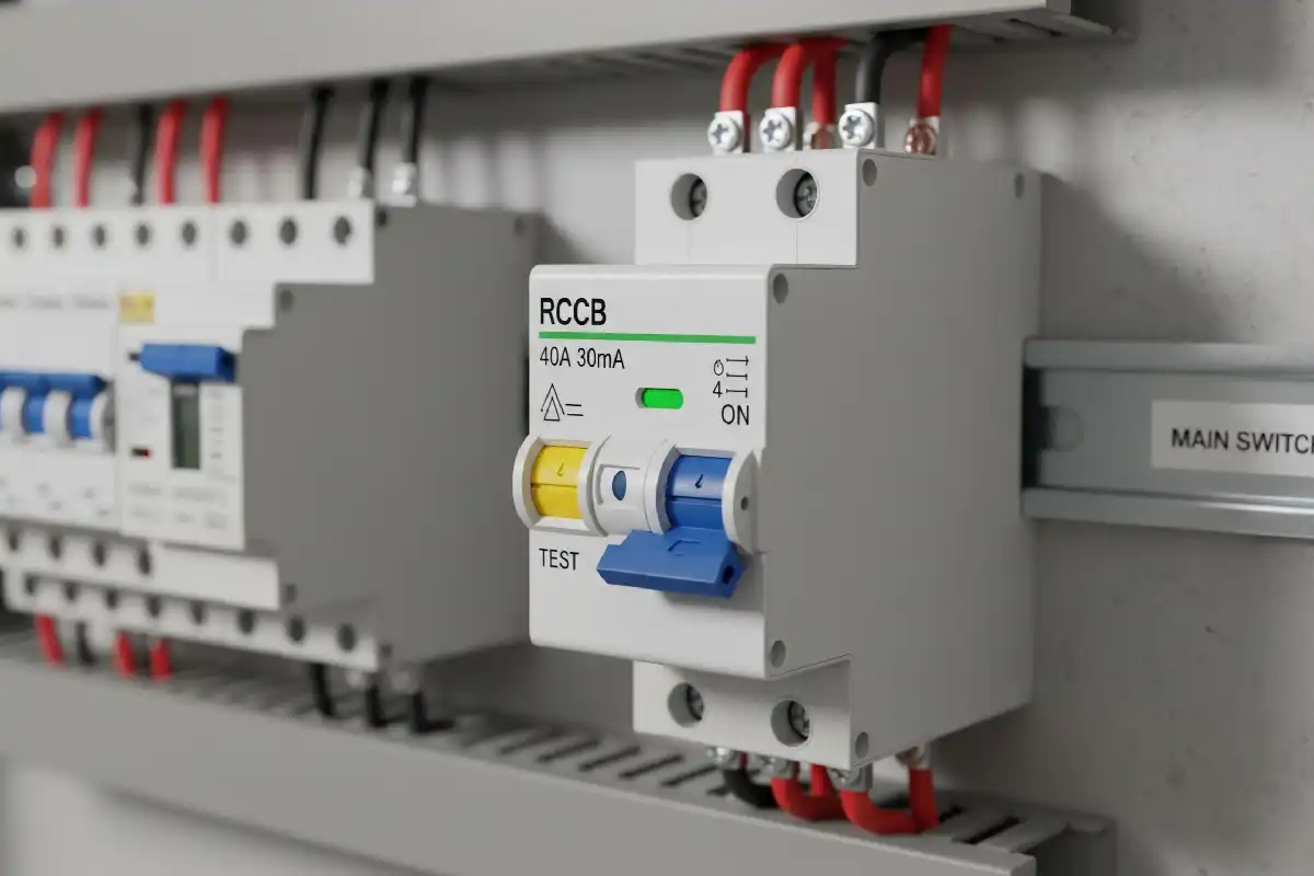
Type A vs Type AC RCD: What Is the Real Difference?
Type AC responds to sinusoidal AC residual current. Type A also responds to specified pulsating DC residual current. That wider capability matters with many electronic loads, but Type A is not a universal answer for drives, EV charging, PV, UPS or smooth DC.
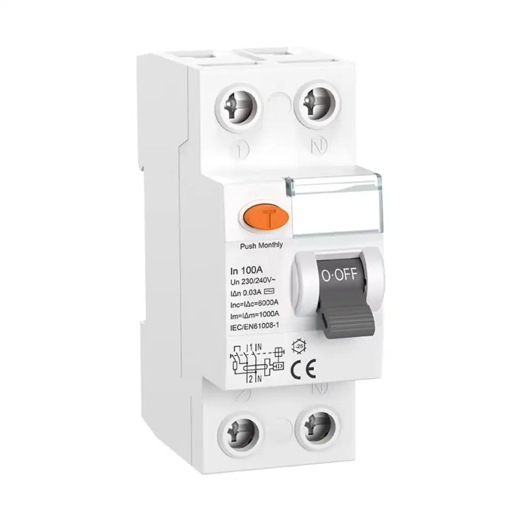
Type A has a wider waveform range than Type AC
A Type AC RCD is intended for sinusoidal AC residual current. A Type A RCD covers that condition and adds specified pulsating DC residual current.
The type letter describes the residual-current waveform the device is designed to recognize. It does not tell you the rated current, residual operating current, number of poles, time delay, short-circuit conditions or whether the product is an RCCB or RCBO.
Type A is often a better starting point for single-phase equipment that contains rectifiers or electronic power supplies. However, the actual load may create smooth DC, composite currents or higher-frequency leakage outside Type A's range. In that case, Type F, Type B or a manufacturer-specified DC-detection arrangement may be needed.
Waveform, sensitivity and product form are separate decisions
- Equal current and IΔn markings do not make Type AC and Type A equivalent.
- Type A's limited smooth-DC immunity is not the same as tripping on every smooth DC fault.
- An RCD never replaces correct earthing, conductor protection, isolation, coordination or maintenance.
The incoming supply can be AC while the fault waveform is not a clean sine wave
Diodes, rectifiers, capacitors, switched-mode power supplies and converters can reshape current inside the load. RCD type addresses the waveform that may appear as residual current.
Sinusoidal AC
The basic waveform for which Type AC is classified. A 50/60 Hz supply label alone does not prove the connected equipment produces only this residual-current shape.
Specified pulsating DC
Rectifier circuits can create a one-directional, varying fault current. Type A adds detection for the specified pulsating DC conditions.
Smooth DC
A smooth DC component can bias a conventional sensing core. Type A has limited immunity, but smooth-DC fault detection belongs to a different capability boundary.
Do not compare the devices by amperes alone
| Selection factor | Type AC RCD | Type A RCD |
|---|---|---|
| Baseline waveform | Designed for residual sinusoidal AC current at the rated power frequency. | Covers the Type AC condition and adds specified pulsating DC residual current. |
| Pulsating DC | Not its intended category Do not assume correct operation when the load can create DC components. | Designed for this condition Applies to the specified waveforms and test conditions in the product requirements. |
| Smooth DC component | Not designed to operate in the presence of DC content, according to ABB's selection guide. | ABB describes operation with up to 6 mA smooth DC superimposed on specified residual currents. This is an immunity limit, not universal smooth-DC detection. |
| Useful load clue | A fixed load known not to create DC residual components, where the local rules and equipment documentation permit. | Some single-phase rectifier and electronic loads whose expected waveform remains inside Type A's defined envelope. |
| What it does not settle | IΔn, rated current, poles, voltage/frequency, delay/selectivity, RCCB versus RCBO, short-circuit conditions, board compatibility and local approval. | |
| Common mistake | Using it for unknown socket loads or modern electronics simply because the supply is AC. | Treating it as a universal option for EV, PV, UPS, VFD or three-phase converters without checking the exact equipment. |
A healthy-looking RCD can still be the wrong type for the load
A DC component can magnetically bias the sensing transformer's core. If the core moves toward saturation, its response to another AC or pulsating residual current can be reduced.
This effect is commonly called DC blinding. It explains why changing only the ampere rating or residual sensitivity does not solve a waveform mismatch.
It also affects upstream coordination. When several electronic circuits and RCDs sit below one upstream device, the designer must consider the capability of the full RCD chain and the possible aggregate DC leakage. A downstream Type A, F or B device does not automatically protect an unsuitable upstream Type AC device from blinding.
Type A is broader than Type AC, but it is not the end of the selection tree
IEC 62423 adds Type F and Type B requirements to the Type A base. The exact load manual and national rules still decide whether those categories or another arrangement apply.
Sinusoidal AC
Consider only for known conditions that exclude relevant DC components and where the applicable rules permit.
AC + pulsating DC
Commonly considered for certain single-phase electronic and rectifier loads within the defined waveform limit.
Composite currents
IEC 62423 addresses certain phase-to-neutral frequency-inverter applications and composite residual currents.
Smooth DC and more
Covers smooth DC and broader frequency conditions defined for Type B. Three phase alone does not automatically require it.
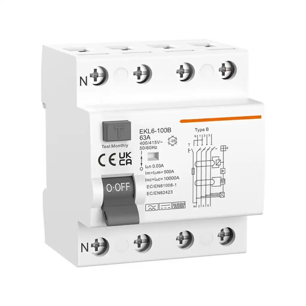
Type B is a distinct capability
A Type B label and waveform symbols show why a Type A device should not be described as an all-current solution.
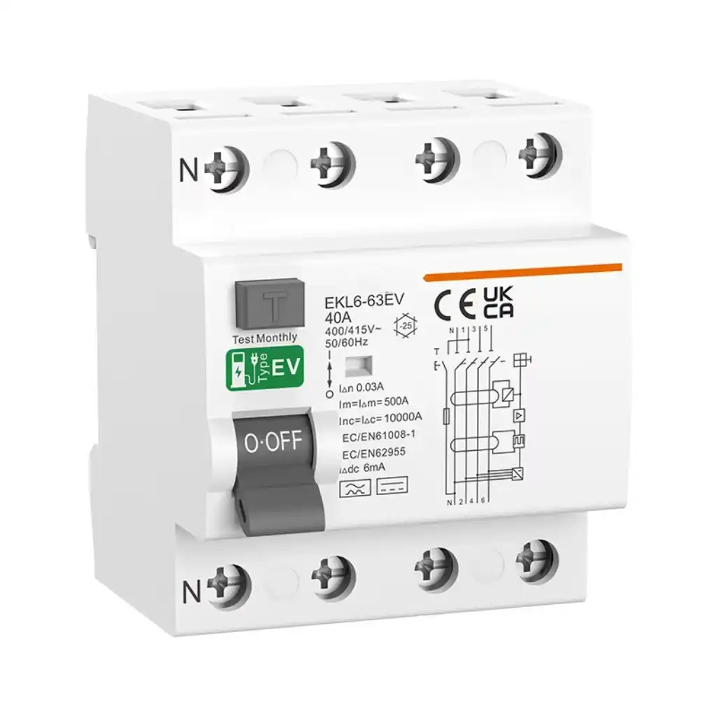
Built-in DC detection changes the route
An EV product may include a specified 6 mA DC detection function. Never transfer that assumption to another charger or RCD.
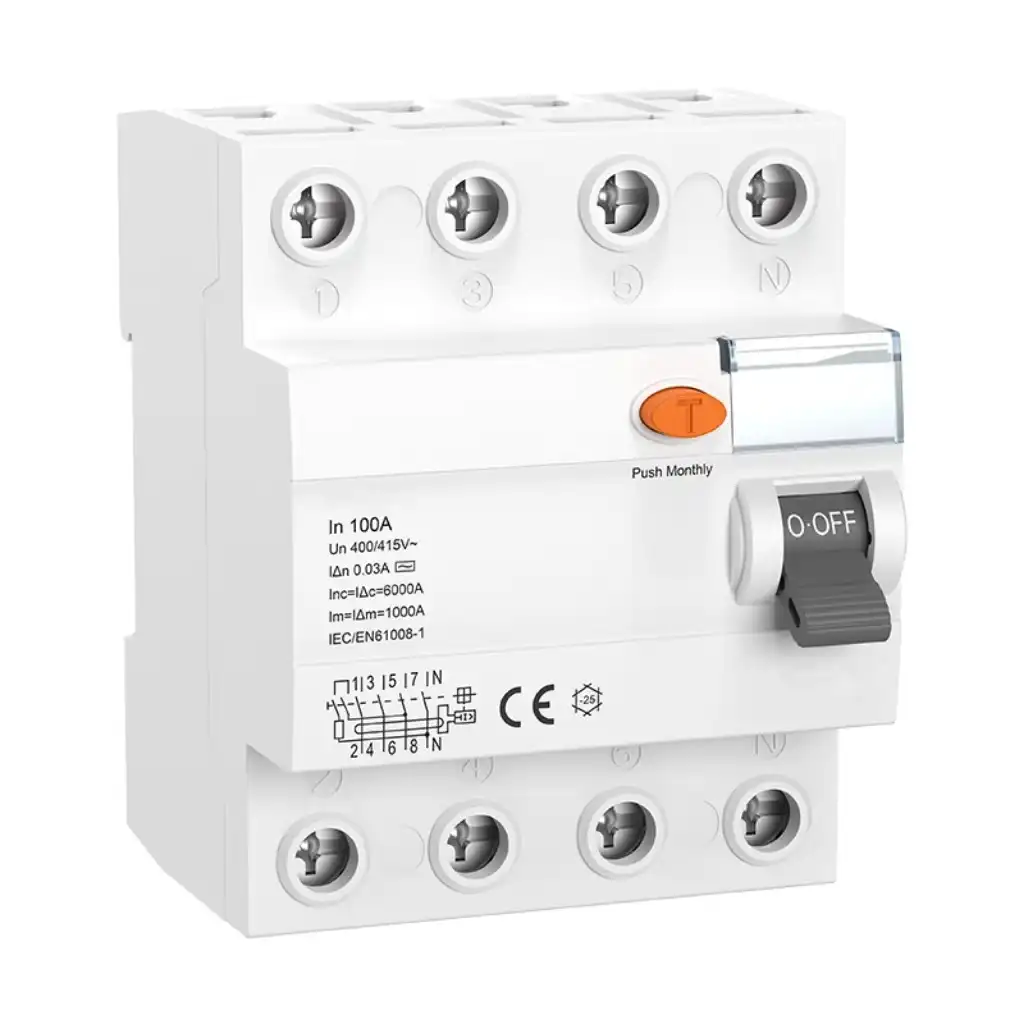
Poles and current do not reveal the type
A four-pole body can belong to different waveform categories. Read the symbol and full data sheet.
Use the product manual to turn a load name into an RCD requirement
“Electronics,” “EV,” “solar,” “UPS” and “drive” are warning labels for further review. They do not identify the final RCD type by themselves.
Simple non-electronic load
Type AC may be acceptable only when the load is known not to introduce DC components and the local rule permits it.
Rectifier or power supply
Type A may fit when the possible residual current remains within its specified AC and pulsating-DC range.
Variable-speed equipment
Some single-phase frequency-inverter loads may require Type F. Follow the exact equipment instructions.
DC detection must be explicit
Check for built-in RDC-DD or DC monitoring, the threshold, the required upstream device and the jurisdiction.
Assess smooth DC and frequency
Type B may be required, but three-phase supply alone is not enough evidence.
Future use changes the risk
Do not treat a general-purpose socket as a known Type AC condition without a defensible load and code assessment.
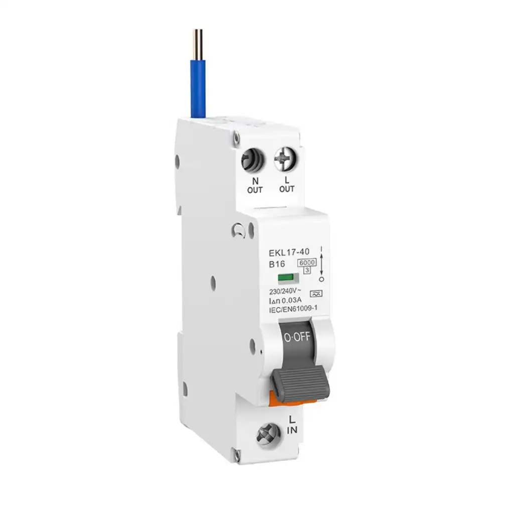
The waveform letter does not tell you whether overcurrent protection is included
RCCB: residual-current protection without integral overcurrent protection. RCBO: residual-current protection with integral overcurrent protection.
IEC 61008-1:2024 covers RCCBs within its stated household and similar-use scope. IEC 61009-1:2024 covers RCBOs within its stated scope. Both product forms may be available in different RCD types, but the real product range and approvals must be checked by exact model.
Do not mix a breaker, RCCB, RCBO, busbar or distribution-board family because the module width appears to fit. Terminals, busbars, heat, short-circuit coordination, product-family compatibility and assembly certification all matter.
Review SENTOP residual current devices →Start with the connected equipment, then work outward through the protection chain
This route is suitable for a preliminary design or RFQ. A qualified person still completes the installation-specific assessment.
Read the load manual
Find the required RCD type, possible DC leakage, built-in DC detection and upstream conditions.
Identify the waveform
Decide whether the load can create sinusoidal AC, pulsating DC, composite, higher-frequency or smooth DC residual current.
Choose AC, A, F or B
Use the load instructions, product data and local installation rule. Do not choose from cost alone.
Set the other ratings
Confirm RCCB/RCBO, IΔn, current, poles, voltage, delay, fault level and backup protection.
Coordinate and document
Review upstream devices, aggregate leakage, neutral routing, board compatibility, testing and future load limits.
The test button is important, but it does not prove the RCD is correct for the circuit
The integral test button checks a built-in functional path. It does not prove waveform suitability, upstream/downstream selectivity, fault-current suitability, neutral routing, conductor design or compatibility with every current and future load.
A device that will not reset, repeatedly trips, shows heat damage, has damaged terminals or fails the required test needs qualified investigation. Do not replace it with a visually similar product based only on pole count and amperes.
- Record the manufacturer, full model, RCD symbol, poles, rated current, IΔn and delay marking.
- List the actual loads and collect their installation manuals.
- Test with the procedures and instruments required by the product and jurisdiction.
- Revisit the RCD choice when a converter, charger, PV inverter, UPS or drive is added.

Ask for a complete protective-device requirement, not “Type A, 63 A”
| Send this information | Why it is needed | Red flag |
|---|---|---|
| Country, supply and installation system | Local rules, earthing arrangement, voltage, frequency and application scope affect the installed solution. | A request for “Type A” with no destination, supply or installation context. |
| Load list and manuals | The equipment defines possible residual-current waveforms and any required RCD/DC-detection method. | Choosing from a generic appliance label instead of exact model documentation. |
| RCD type and product form | Separates AC/A/F/B waveform capability from RCCB/RCBO overcurrent function. | Assuming every RCD includes overload and short-circuit protection. |
| Ratings and poles | Confirm IΔn, rated current, voltage, frequency, conductor arrangement, delay and short-circuit conditions. | Matching only the ampere number. |
| One-line diagram | Shows upstream/downstream RCDs, neutral routing, backup protection and selectivity needs. | Adding a more capable downstream device without reviewing the upstream RCD. |
| Board compatibility and test plan | Connects the device to the approved busbar, enclosure, documents, commissioning and handover process. | Mixing families because the DIN-rail dimensions look similar. |
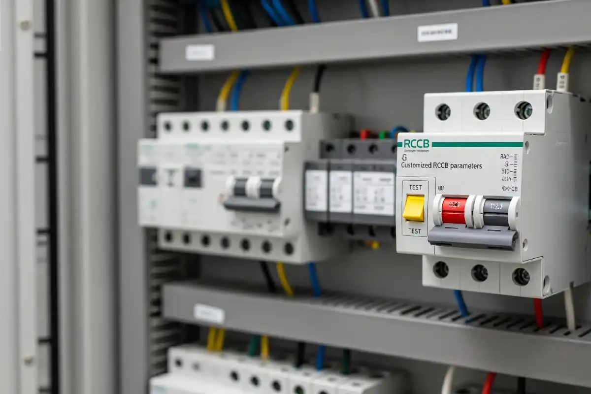
Use Type AC only for a known Type AC condition
Use Type A when the expected residual current requires its pulsating-DC capability and remains within the device's stated limits.
For uncertain electronic loads, frequency conversion, EV charging, PV, UPS or possible smooth DC, do not make the decision from Type AC versus Type A alone. Identify the actual equipment requirement, check whether Type F, Type B or an approved DC-detection arrangement is needed, and coordinate every upstream device.
For procurement, keep the approved sample, complete model, rating schedule, data sheet, certificate scope, label artwork and order record together. A similar case does not prove an equivalent protective function.
Use the next resource for the next selection question
Short answers to the questions buyers ask first
What is the main difference between Type A and Type AC RCDs?
Type AC is designed for sinusoidal AC residual current. Type A covers that condition and adds specified pulsating DC residual-current detection. Type A also has a limited smooth-DC immunity condition; that does not make it a general smooth-DC detector.
Is a Type A RCD always better than Type AC?
Type A has broader waveform capability, but the correct choice depends on the load, local rules and full protective system. Type F or Type B may be required for residual-current conditions outside Type A's range.
Can I use a Type AC RCD with electronics?
Do not assume so. Electronic equipment can contain rectifiers or switching stages that produce residual-current components outside Type AC's intended condition. Check the exact equipment manual and local installation requirements.
Does a Type A RCD detect smooth DC leakage?
Not as a general rule. Type A detects specified pulsating DC residual current and has limited smooth-DC immunity under stated conditions. ABB describes operation with up to 6 mA smooth DC superimposed on specified residual currents; higher or different smooth-DC conditions may require another arrangement.
What is DC blinding of an RCD?
DC blinding is the reduction of a conventional RCD sensing core's response when a DC component biases or saturates the magnetic core. It is a waveform and coordination problem, not something solved by selecting a higher ampere rating.
Is Type A enough for an EV charger?
Sometimes, but never assume it. The charger manual and local rules may require Type B, Type A or F with a compliant residual direct-current detection device, or another arrangement. Verify the charger's built-in protection and the required upstream RCD.
What is the difference between an RCCB and an RCBO?
An RCCB provides residual-current protection without integral overcurrent protection. An RCBO includes integral overcurrent protection. Both still need the correct RCD type, ratings, poles, short-circuit suitability and assembly compatibility.
Does the RCD test button prove the RCD is correct for the circuit?
No. The test button checks a built-in functional path. It does not prove waveform suitability, upstream/downstream coordination, fault-current suitability, neutral routing or compatibility with every connected load.
How do I identify Type A or Type AC on an installed RCD?
Read the front waveform symbol, full model number, data sheet and manufacturer documentation. Also verify IΔn, rated current, poles, delay, RCCB or RCBO function and board compatibility because these are separate from the RCD type.
Sources used to define the capability boundaries
Standards define product requirements; national installation rules and equipment instructions define the installed solution. Manufacturer guides below are interpretation aids, not substitutes for either.
- IEC 61008-1:2024 - general rules for RCCBs without integral overcurrent protection within its stated scope.
- IEC 61009-1:2024 - general rules for RCBOs with integral overcurrent protection within its stated scope.
- IEC 62423:2009 - Type F and Type B requirements additional to Type A device requirements.
- ABB RCD Technical Guide - AC, A, F and B waveform comparison and selection factors.
- ABB guide to RCDs connected in series - DC blinding, limited immunity and upstream/downstream coordination.
- ABB residual current devices - Type A pulsating-DC capability and 6 mA smooth-DC condition.
- Electrical Safety First wiring guidance - UK-specific Type AC, inspection and testing context.
- Hager selection of RCD types - application examples and concise AC/A/F/B boundaries.
Have a load manual, RCD photo, one-line diagram or project BOM to review?
Send the destination country, supply system, load list, required RCD type, IΔn, current, poles, upstream protection, panel family, quantity and certificate needs. SENTOP can help organize the information needed for an RCCB or RCBO quotation.
