
Find every source
Review normal supply, generator, UPS, photovoltaic, control-power, stored-energy and backfeed paths.
Qualified-person installation guide
Installing the breaker is more than snapping a clip onto metal. The safe job includes product and panel compatibility, energy control, mounting, correct termination, inspection, testing and documentation.
To install circuit breakers on DIN rails, a qualified person first confirms the exact breaker and complete assembly are compatible. They then isolate and verify the circuit is de-energized, mount the breaker by its specified hook-and-latch method, terminate it to the documented conductor and torque limits, restore barriers, test the assembly and re-energize under the approved procedure.
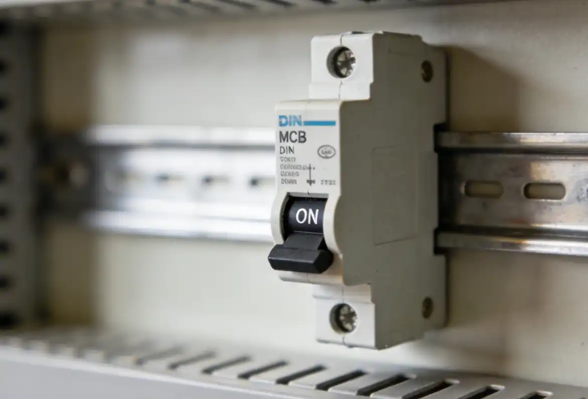
A rail clip proves only mechanical retention. The complete installation must pass four separate checks.
This is an IEC-oriented workflow for modular MCBs, RCBOs and similar DIN-mounted protective devices. It explains the safe sequence and the checks that cannot be guessed.
It is not an energized-work procedure, a universal wiring diagram, a cable-sizing table or an approval for a particular panel. A qualified person must use the exact breaker instructions, enclosure or panel documentation, circuit design and locally adopted rules.
A modular DIN-rail MCB normally has a rear clip designed for a stated rail profile. A plug-on or bolt-on panelboard breaker uses a different mounting and bus connection system. Do not adapt one architecture to the other.
IEC 60715:2017 defines dimensional and functional requirements for compatible mounting on standardized rails.[1] The common top-hat form is often called a 35 mm rail. This standardization helps mechanical mounting. It does not make different breakers, comb busbars, auxiliaries or enclosures electrically interchangeable.
Still verify voltage, poles, current rating, trip curve, breaking capacity, conductor range, thermal limits, accessories, touch protection and complete panel authorization.
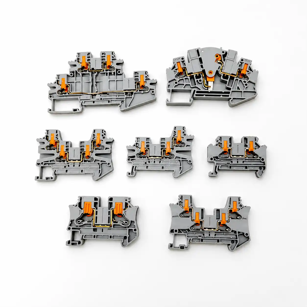
| Device architecture | How it is retained | What you must verify |
|---|---|---|
| DIN-rail MCB or RCBO | Rear hook and spring clip or latch on a compatible rail | Rail profile, breaker ratings, enclosure, terminals, approved busbar and accessories |
| Plug-on panelboard breaker | Mounting rail plus jaws that engage a named panel bus | Panelboard label, breaker family, bus type, available fault current and installation instructions |
| Bolt-on panelboard breaker | Mechanical mounting plus a bolted bus connection | Named panel interior, fasteners, torque, dead-front and branch connector requirements |
Schneider Electric’s current NQ panelboard instructions show why the distinction matters: the named QO/QOB breakers use a panel-specific mounting rail and branch connector, plus prescribed covers, fillers and torque information.[9] That is not a generic DIN-rail retrofit method.
Treat exposed parts as energized until a qualified person has followed the applicable energy-control procedure and verified the de-energized condition.
For U.S. workplaces within its scope, OSHA 1910.333 requires exposed live parts to be de-energized unless a stated exception applies. It also requires locks or tags as specified and verification with test equipment by a qualified person.[2] OSHA separately explains that an LED indicator is not a substitute for testing the circuit parts that may be touched, including checks for backfeed or induced voltage.[3]
Review normal supply, generator, UPS, photovoltaic, control-power, stored-energy and backfeed paths.
Use the approved upstream disconnect and the site’s lockout/tagout or equivalent energy-control method.
Use suitable, properly rated test equipment and the required test method. A handle position is not proof.
Stop the job if supply-side parts remain exposed and live, the isolation point is unclear, the fault level is unknown, the panel is damaged, the breaker history is uncertain or the work changes the protection design.
The sequence below keeps model-specific data where it belongs: in the exact breaker, accessory and panel instructions.
Match the breaker part number to the schematic and bill of materials. Confirm AC or DC, voltage, poles, rated current, trip characteristic, breaking capacity, load and conductor protection, coordination, enclosure and destination-market requirements.
Output: approved device and circuit referenceReview the single-line diagram, panel schedule and equipment labels. Include alternate sources, control circuits, stored energy and possible backfeed. Decide which upstream disconnect makes the work area safe.
Output: site-approved isolation planFollow the applicable energy-control procedure. A qualified person then verifies the parts to be worked on are de-energized with suitable test equipment. Address induced voltage and unrelated backfeed.
Do not proceed on an OFF handle or indicator aloneCheck that the rail is secure, straight and free from corrosion, burrs, paint buildup or obstruction. Inspect the breaker housing, terminals, latch and label. Confirm cover clearance, wire-bend space, end stops and required blanking parts.
Reject cracked, contaminated or damaged partsMany modular devices use a hook-and-latch action. Engage the fixed part of the rear clip with the correct rail edge. Pivot or press the device toward the rail until the moving latch engages. Follow the product drawing because the exact motion varies.
Never strike or force the housingThe breaker should sit square and should not rock, lift or slide unexpectedly. If it does not lock cleanly, stop. Check for the wrong rail profile, a damaged latch, interference, a loose rail or an incorrect sequence.
Do this before conductors make later removal harderUse the stated conductor material and range, strip length, ferrule rule, terminal entry and number of conductors. Fit only approved fork, pin or other comb busbar components with their end caps and covers. Tighten with a calibrated torque tool to the exact product value.
Do not copy torque or busbar parts from another seriesFit auxiliaries, residual-current modules, terminal shields, dead-front parts and unused-way fillers in the documented order. Confirm RCBO or RCCB neutral paths, test functions and line/load requirements from the exact instructions.
Touch protection must be complete before energizationComplete the approved visual, mechanical and electrical test plan. Restore all doors and covers. Follow the authorized re-energization sequence, keep people clear and watch for abnormal indication, odor, noise, heat or tripping. Update the panel schedule, drawings, part number, torque and test record.
The job ends with records, not with the first successful ON operationUse the exact manufacturer data for conductor material, rigid or flexible construction, ferrules, strip length, terminal entry, number of conductors and tightening torque. A wire that enters the terminal is not automatically an approved connection.
| Official product example | Published mounting / torque data | What the example teaches |
|---|---|---|
| ABB S 200 S | 35 mm DIN rail fast clip; 2.8 N·m terminal torque[4] | Rail and torque are stated for a named family, not every MCB. |
| Eaton PLSI | 35 mm DIN channel, two-position clamp; 2 N·m[5] | A similar rail format can still have different terminal data. |
| Schneider Acti9 iC60H | 2 N·m for 1–25 A; 3.5 N·m for 32–63 A in the cited table[6] | Torque can change within one product family as the rating changes. |
The table demonstrates variation. Use the label or current instruction sheet for the exact catalog number, terminal and accessory combination in front of you.
Need to confirm whether the project calls for an MCB or a larger molded-case device? Review the SENTOP MCB vs MCCB comparison. For enclosure planning, use the exact distribution box and breaker documentation together.
Use this as a planning aid before the formal inspection and test record. Checking every box does not authorize energization.
Each item needs evidence from the actual panel, breaker instructions, circuit design or test plan.
Diagnose the cause while the assembly is in a verified safe state. Do not force, shim or energize around a mechanical problem.
Check the rail profile, clip orientation, latch position, adjacent-device interference and physical damage. Compare the product drawing with the actual parts. Do not strike the housing or file the clip.
The latch may not be fully engaged, the rail may be loose or bent, or required retention hardware may be missing. Correct the root cause before wiring or energizing.
De-energize and have qualified personnel investigate. Possible causes include wrong torque, conductor mismatch, strand damage, overload, poor busbar contact or a damaged terminal. Do not simply retighten a heat-damaged connection and return it to service.
Review measured inrush, the load, conductor and fault design, and the breaker’s time-current curve. A fault or wiring error may also exist. Do not increase the current rating or change B, C or D curve as a casual fix.
Device depth, wire bend, accessories or rail position may be outside the approved layout. Rework the arrangement with compatible components. Never energize with a required barrier omitted.
Before removing a breaker, repeat the energy-control and voltage-verification process. Disconnect conductors and accessories as instructed, operate the correct latch and support the wiring. A replacement must match every relevant electrical and assembly field—not only the ampere value.
Send enough information to keep model selection, installation and future replacement tied to the same approved design:
No. Use only a breaker designed for the stated rail and approved for the complete enclosure or panel arrangement. A rail clip does not prove voltage, breaking capacity, busbar, terminal or panel compatibility.
Many modular MCBs and RCBOs use a 35 mm top-hat rail described under IEC or EN 60715. The exact breaker instructions still control the accepted rail profile, mounting method and enclosure arrangement.
No. The work area must be placed in a verified de-energized condition under the applicable energy-control procedure. The correct isolation point may be upstream, and a qualified person must test the parts that could be contacted.
Use the value marked on the exact device or stated in its current instruction sheet. Do not copy torque from a similar breaker. Use a calibrated torque tool and follow any project recording requirement.
No. Confirm the approved breaker series, pole pitch, fork or pin form, rated current, terminal arrangement, end caps, touch protection and installation sequence.
Common causes include the wrong rail profile, a damaged or blocked clip, a bent or loose rail, adjacent-device interference or the wrong mounting sequence. Do not force it; correct the incompatibility first.
The assembly, device and local rules determine the test plan. It commonly includes visual and mechanical inspection, torque and label confirmation, plus applicable continuity, insulation, polarity, functional, RCD or RCBO, loop, fault or protective-device tests.
Safety notice: This page explains a controlled workflow; it does not authorize DIY electrical work or work on energized equipment. Always follow the exact manufacturer instructions, the approved panel or enclosure design, the site safety program and the rules that apply in the installation location.
If any required document, rating, test result or isolation control is missing, stop. A purpose-built, documented assembly is safer than a part that merely appears to fit.
Send SENTOP the breaker model or required ratings, single-line diagram, enclosure and rail details, busbar or accessories, conductor data, quantity, destination and required certification package.
