
01
Conductors connected
List L or L1/L2/L3, N and PE separately from the one-line diagram. A distributed neutral makes the neutral decision visible; it does not make the decision for you.
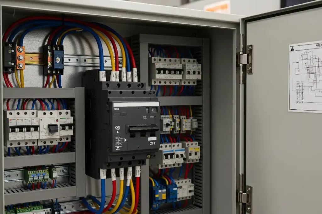
Choose the breaker from the conductors and the neutral requirement—not from the abbreviation alone. SP usually protects one line conductor. TP/3P covers three phase conductors. TPN/3P+N adds a neutral path whose switching and protection must be confirmed. 4P proves four poles, but it does not by itself prove what the fourth pole does.
A pole is a current path through the device. A multi-pole breaker normally operates its poles together, but every pole does not necessarily have the same overcurrent release. That is why a four-module device and a four-protected-pole device are not automatically the same thing.
State which conductors are connected, which conductors are switched, and which conductors receive overcurrent protection. Then add the device family, voltage, breaking capacity, trip data and required standard.
For example, “63 A TPN breaker” leaves the supplier to interpret too much. “3P+N, three protected phase poles plus a switched neutral, neutral marked N, exact sequence per the manufacturer drawing” is much clearer.
List L or L1/L2/L3, N and PE separately from the one-line diagram. A distributed neutral makes the neutral decision visible; it does not make the decision for you.
Define which current-carrying conductors must open together for protection, isolation, maintenance or source transfer. Confirm any neutral make/break sequence from the exact product documentation.
Check which poles contain thermal-magnetic or electronic overcurrent protection. Four physical poles do not automatically mean four protected poles.
Usually one ungrounded conductor is switched and protected. It is not the same statement as 1P+N.
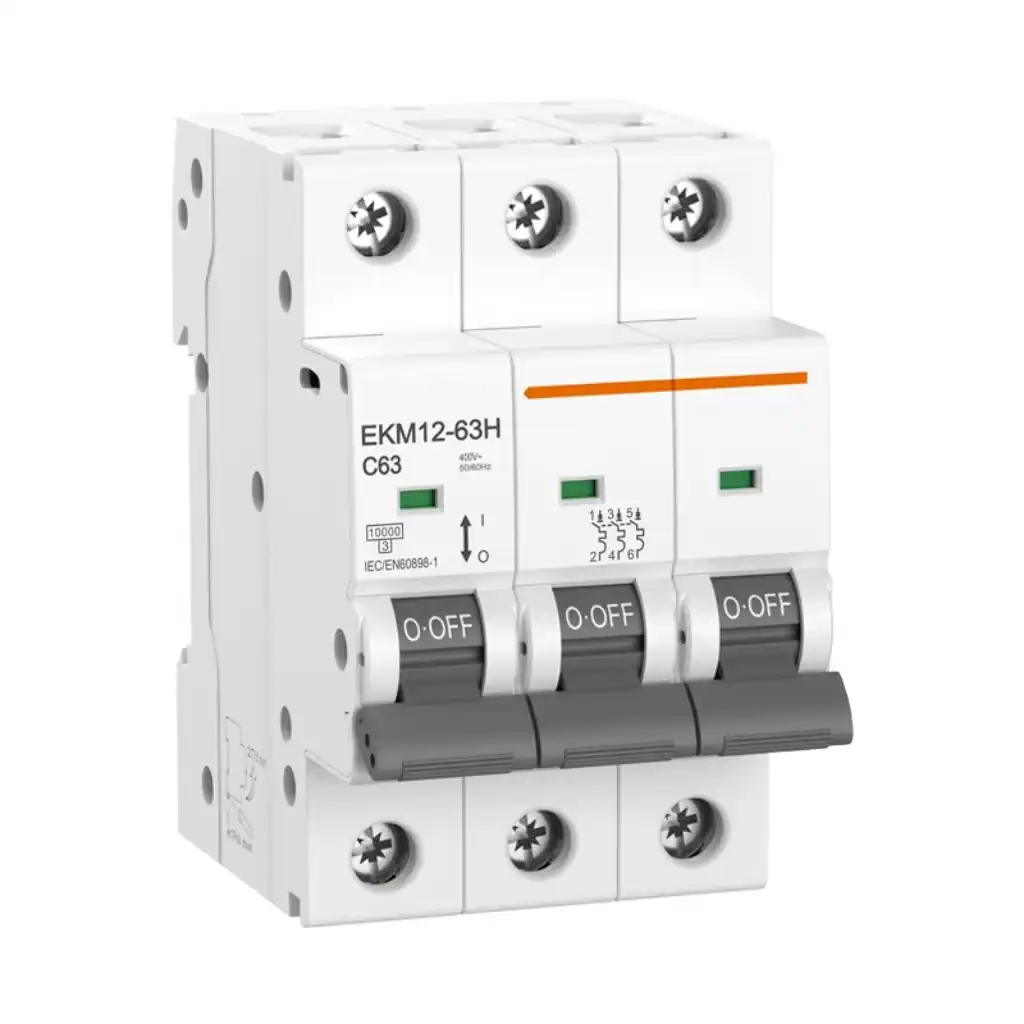
Verify: system voltage, line/neutral arrangement and one-pole breaking capacity.Three linked phase poles. This is the normal topology starting point for many three-wire motors and feeders.
Verify: common-trip construction, load duty, voltage and fault rating.Commonly describes three protected phase poles plus a neutral path. The neutral may be solid, switched or handled differently by the product.
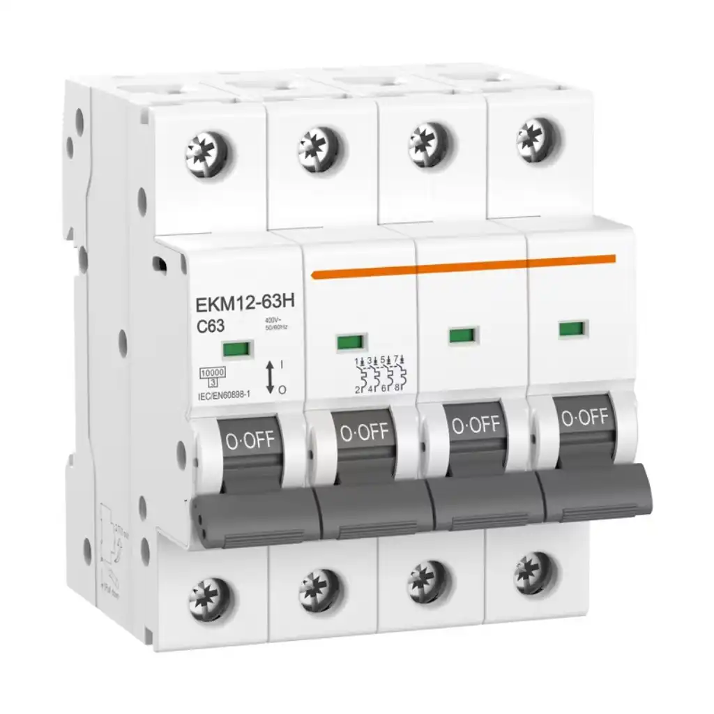
Verify: N marking, protected-pole count and neutral sequence.Four current paths in one device. The fourth pole can be protected, switched without an overcurrent release, or configured by the product family.
Verify: fourth-pole function; never infer it from width or label alone.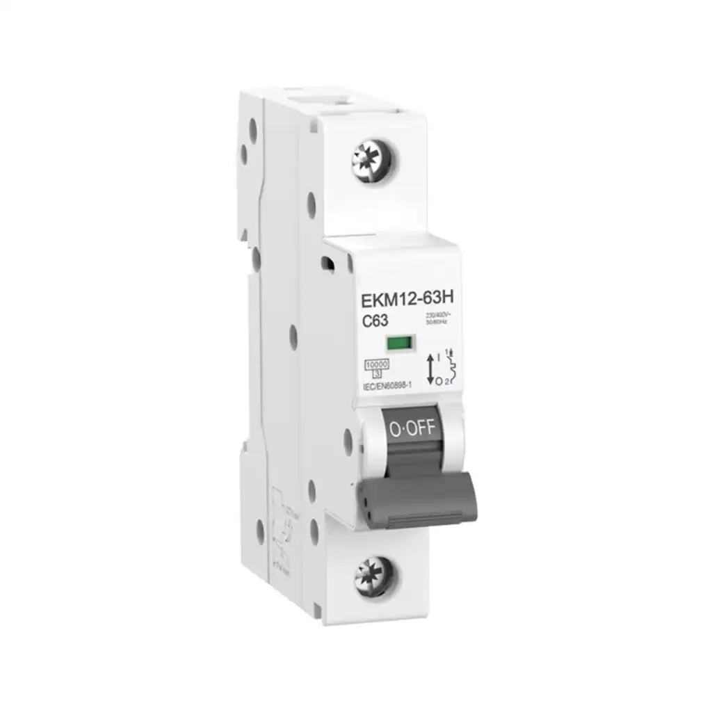
The examples below explain selection logic for low-voltage AC distribution. They do not replace the project one-line diagram, applicable code or certified product instructions.
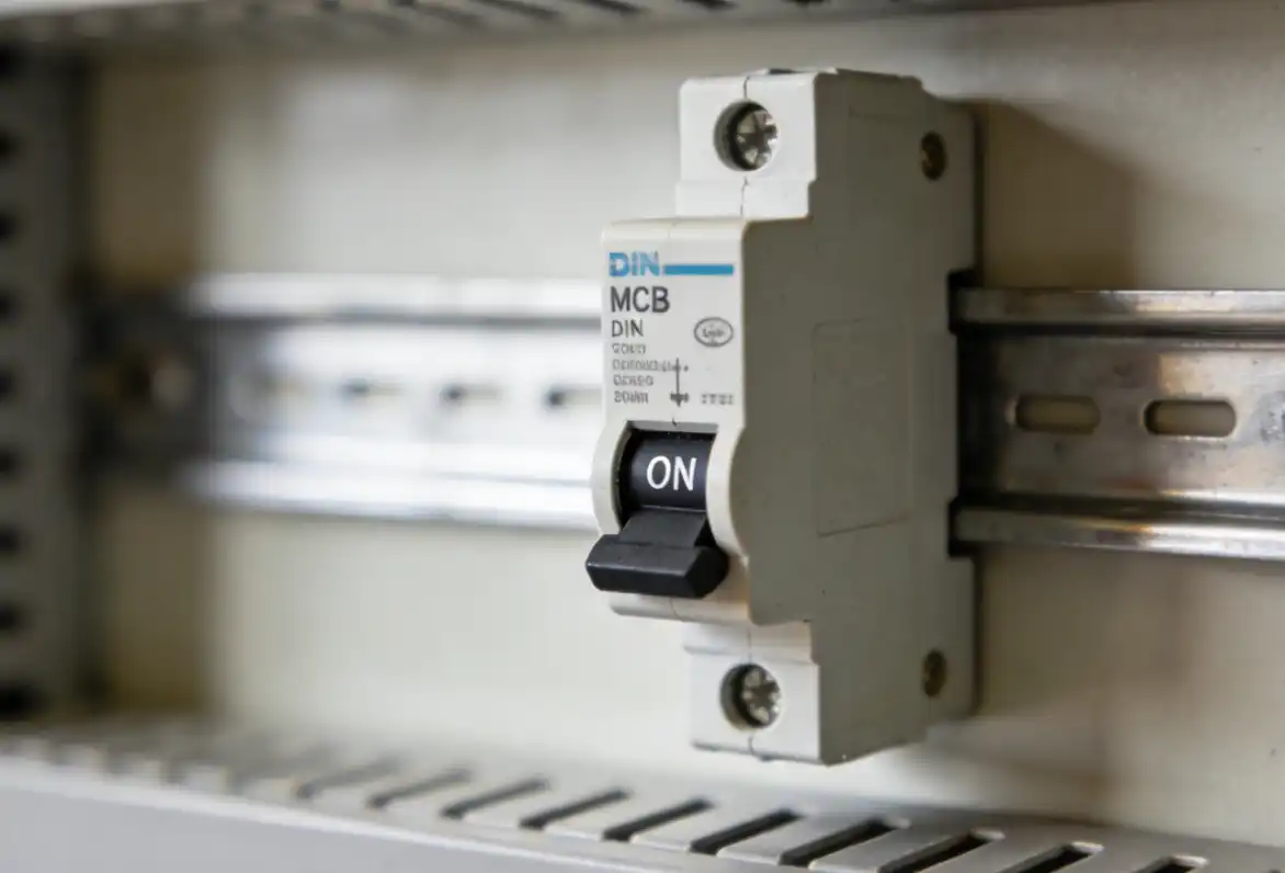
An SP or 1P breaker is normally used where one circuit conductor is to be protected and switched. In a conventional single-phase branch circuit, this is often the line conductor while the neutral is managed by the installation arrangement. That statement is not universal across every supply system or jurisdiction.
A 1P+N device is a different description. It may provide overcurrent protection in the line path while also switching a neutral path. Before substitution, check the manufacturer diagram, line and neutral markings, permitted supply direction, busbar compatibility and any residual-current sensing path.
TP and 3P commonly describe linked paths for L1, L2 and L3. A three-phase motor without a load neutral often begins with this topology because all three phase conductors must be interrupted together. The final device may be an MCB, MCCB or a motor-protection architecture depending on current, starting method, fault level and coordination.
Do not use the letters TP to decide product class. IEC 60898-1 applies to AC overcurrent breakers for household and similar installations within its stated limits. IEC 60947-2 covers industrial circuit-breakers within its scope. The product standard, rated voltage and test data must match the installation.
Do not assume so. A three-phase circuit may require verified common trip and linked operation. Three unrelated single-pole devices can fail the assembly, tripping and certification requirements.
TPN is common trade language for three phase and neutral. It can describe a distribution board, incomer or breaker arrangement. Use it to start a technical conversation, not to finish a purchase specification.
A product described as 3P+N may provide three protected phase poles plus a neutral pole used for switching. For some product families, the N pole is marked and intentionally closes before the phases and opens after them.
A 4P device can have four identical protected poles. Another four-pole industrial breaker can have three protected phase poles and an unprotected, half-protected or fully protected neutral arrangement selected through its release system.
“3P+N, three protected phase poles plus switched neutral; neutral marked N; exact make/break sequence per manufacturer drawing; common operation; standard, rated voltage, breaking capacity and trip function as specified.” If four overcurrent-protected poles are required, write “four protected poles” explicitly.
MCB, MCCB, RCCB and RCBO do different jobs. A four-pole RCCB does not become an overcurrent breaker simply because it has four current paths.
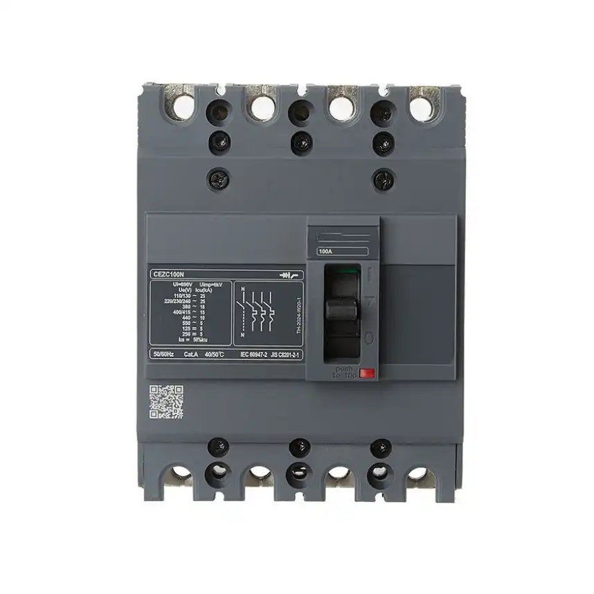
Used for industrial or larger distribution duties with product-specific releases and accessories. Verify Icu and Ics at the actual voltage, protected-pole configuration, neutral settings and coordination.
View SENTOP MCCB selection page →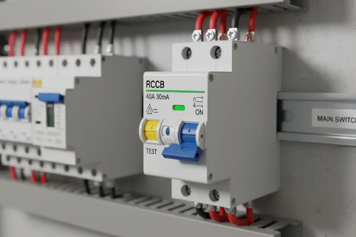
IEC 61008-1 defines an RCCB without integral overcurrent protection. Choose waveform type, IΔn, poles and installation conditions, then provide coordinated overcurrent protection.
View SENTOP RCCB selection page →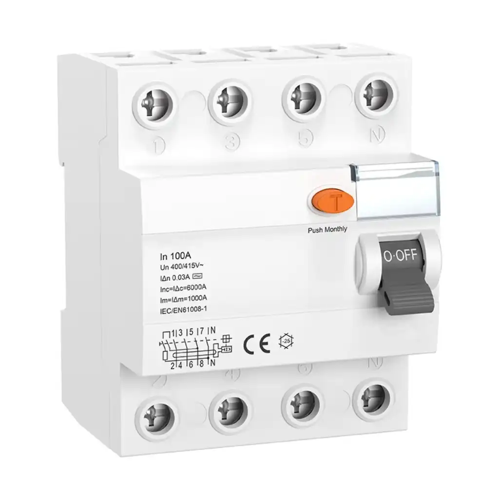
IEC 61009-1 defines an RCBO with integral overcurrent protection. Pole count comes after the residual-current type, IΔn, overcurrent characteristic, supply conditions and neutral routing are established.
Review residual-current device guidance →| Device family | Primary function | What pole selection must still confirm |
|---|---|---|
| MCB | Overload and short-circuit protection within the product's rated application and standard. | Protected and switched paths, Ue, trip curve and Icn at the actual voltage. Module count does not define neutral behavior. |
| MCCB | Industrial overcurrent interruption and protection, often with adjustable releases and accessory options. | 3P, 3P+N or 4P construction; neutral release setting; Icu/Ics; isolation suitability; terminals and coordination. |
| RCCB | Residual-current protection without integral overcurrent protection under IEC 61008-1. | Conductors included in sensing and switching, RCD type, IΔn, voltage conditions and associated overcurrent protection. |
| RCBO | Residual-current protection with integral overcurrent protection under IEC 61009-1. | RCD characteristics and overcurrent data, plus the exact line/neutral paths and pole arrangement. |
| Switch disconnector | Manual switching and isolation as rated; not automatically an overcurrent protective device. | Neutral sequencing, utilization category, isolation rating and whether a separate protective device is required. |
These examples show how to frame the choice. They are not project approvals and do not create a universal rule for neutral switching.
L1, L2 and L3 feed the motor. TP/3P is the topology starting point, but the final protection may also require a motor-protection breaker, overload relay, contactor and tested coordination for the starter duty.
Start with: 3P topology + motor and fault-duty review.The feeder distributes L1, L2, L3 and N to phase-to-phase and phase-to-neutral loads. The designer must decide whether N is solid, switched or protected after reviewing earthing, neutral current, harmonics and local rules.
Start with: explicit 3P+N or 4P functional statement.Choose the RCD architecture, waveform type and sensitivity first. If overcurrent protection must be integral, investigate an RCBO. If an RCCB is selected, coordinate the required upstream or associated overcurrent protective device.
Start with: RCD function + conductor sensing/switching path.Neutral switching can change earthing and system behavior. Use a listed or certified transfer architecture with the required interlocking, pole arrangement and project-specific earthing analysis. A generic breaker table cannot settle this design.
Start with: source-transfer scheme + responsible engineer review.Source transfer adds interlocking, switching duty, control logic and sometimes a specific neutral arrangement. Select the transfer scheme as a complete system, then verify the exact pole configuration.
Product image: SENTOP automatic transfer switch range.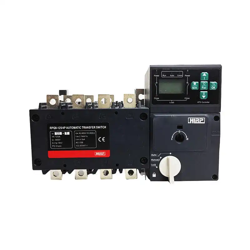
Use this sequence at concept stage, during quotation review and again before approving a delivered model. It keeps system design, protection and procurement evidence connected.
Record source type, phase count, nominal voltage, frequency, earthing arrangement, prospective short-circuit current and whether the circuit is single-source, generator-backed, UPS-fed or otherwise multi-sourced.
Write L or L1/L2/L3, N and PE separately. Show where neutral is distributed and where protective earth is bonded. Never count PE as a breaker pole.
Define overload, short-circuit, residual-current, manual isolation, emergency switching, remote trip, metering and source-transfer needs. One device may not safely provide all functions.
State whether N is absent, solid, switched, sequenced or protected. Base the requirement on the project design, earthing system, load assessment and applicable rules.
Choose MCB, MCCB, RCCB, RCBO or switch disconnector for its actual duty. Then select 1P, 3P, 3P+N or 4P from the schematic—not from a catalogue shortcut.
Check ratings at installed conditions, busbar and accessories, nameplate, wiring diagram, model suffix and certification. Preserve approved drawings, test evidence and change-control records.
| Datasheet item | What to inspect | Why it changes the decision |
|---|---|---|
| Pole description | Exact wording: 1P, 1P+N, 2P, 3P, 3P+N or 4P; number of protected poles; L/N terminal marking. | Catalogue headings can hide different internal arrangements. The exact suffix and schematic control. |
| Wiring diagram | Internal current paths, N position, incoming/outgoing terminals, permitted supply direction, pole sequence and common trip. | This is the fastest evidence that a TPN or 4P offer matches the project requirement. |
| Rated operational voltage | Ue by pole configuration and AC/DC condition, not only the product-family maximum. | Voltage rating and short-circuit performance can change with topology and operating voltage. |
| Breaking capacity | Icn for applicable MCB data or Icu/Ics for industrial breaker data, stated at the actual voltage and test standard. | The selected rating must cover the prospective fault current or a documented backup arrangement. |
| Trip or release data | Thermal-magnetic curve or electronic settings, including any neutral release, N/2, N or oversized-neutral function. | Equal current labels do not prove equal overload, short-circuit or neutral performance. |
| Residual-current data | RCCB/RCBO type, IΔn, time delay or selectivity, supply-voltage dependence where applicable and wiring conditions. | Pole count does not define leakage-current compatibility or the complete shock-protection design. |
| Panel integration | Isolation suitability, terminals, busbars, lugs, auxiliary contacts, shunt/undervoltage release, interlocks, pitch and clearances. | A compliant breaker can still be unsuitable for the assembly or fail accessory compatibility. |
Icu and Ics reminder: under IEC 60947-2 terminology, Icu is the rated ultimate short-circuit breaking capacity and Ics is the rated service short-circuit breaking capacity. Read both at the stated operational voltage. Neither value proves how the neutral pole is protected.
A clear RFQ lets suppliers compare the same functional arrangement. It also reduces the chance that a familiar-looking four-pole frame is accepted as an equivalent product.

The delivered breaker should match the approved part number, pole construction, ratings, accessories and documentation. Inspect the nameplate and terminal diagram, then perform the commissioning checks required by the project.
Application image: SENTOP distribution box page.Use the relevant product family page to define ratings, then keep the one-line diagram and functional pole description attached to the enquiry.
Review DIN rail MCB poles, trip curves, voltage and breaking capacity.
Prepare MCCB frame, release, Icu/Ics, accessories and pole requirements.
Review RCCB type, IΔn, poles, upstream protection and application data.
Choose the protective-device class from system duty before choosing poles.
Review operating method, source arrangement, poles, current and neutral treatment.
Organize model review, sample approval, labeling, documents and repeat orders.
Use these answers to identify what must appear on the schematic, datasheet and purchase description.
No—not as a universal rule. TPN commonly describes a three-phase-and-neutral arrangement, while 4P states that the device has four poles. A 3P+N product may have three protected phase poles plus a switched neutral. A 4P product may have four identical protected poles or another neutral arrangement. Verify the exact wiring diagram and protected-pole statement.
No. Some four-pole devices provide four protected poles, while other four-pole configurations have three protected phase poles and a switched or differently protected neutral. The trip-unit data, wiring diagram, certification and terminal marking—not the label 4P alone—show the neutral function.
Use a TP/3P topology when three phase conductors must be protected and disconnected together, as in many three-phase three-wire motor or feeder circuits. This is only the topology starting point. Verify the breaker class, current setting, voltage, short-circuit rating, curve or release and coordination.
Do not assume so. A three-phase circuit may require common trip and linked operation verified by the protective device's design and certification. Three separate SP breakers may not provide the required tripping, handle operation, short-circuit behavior or approved assembly.
It generally means three phase poles plus a neutral path, but it does not settle the neutral details. A product may have three protected phase poles and a switched neutral, while another family may differ in neutral protection, sequencing, terminals or rating. Check the exact model code and official diagram.
It depends on the circuit conductors, RCD architecture, local requirements and intended protection scheme. A three-phase four-wire circuit may need an RCD arrangement that includes the relevant conductors, but RCD type, sensitivity, upstream protection, neutral routing and product instructions also control the choice.
No. Under IEC household-and-similar-use terminology, an RCCB provides residual-current protection without integral overcurrent protection. An RCBO includes integral overcurrent protection. Both can be available in different pole configurations, but their protection functions remain different.
Send the one-line diagram, voltage and frequency, earthing arrangement, fault level, load type, required standard, current or setting, breaking rating and an explicit statement of phase and neutral behavior. Ask for the exact datasheet, wiring diagram, protected-pole information, accessory compatibility and certification evidence.
The sources below support device-scope definitions and the central warning that pole count alone does not prove neutral protection. Project rules and exact product documentation still control final selection.
Reviewed 16 August 2026. Standards and manufacturer documents can be revised. Confirm the edition, target-market acceptance and exact product reference during project approval.
Share the one-line diagram, voltage, fault level, load, required standard, protected poles, neutral function, accessories, quantity and destination. SENTOP can help organize the technical requirements for product-family and model review.
