
Define the circuit in one sentence
State AC or DC, supply voltage, phase arrangement, grounded or neutral conductors, one load or multiple circuits, design current and load type.
Circuit protection decision guide
Sometimes—but the answer depends on the exact breaker, supply system and approved wiring arrangement. Pole count alone is not enough.
A 3-pole breaker may protect one two-conductor load only when the manufacturer permits that use. Every electrical rating must still fit. One ordinary 3-pole breaker cannot replace two independent 2-pole circuits.
People use “two-pole circuit” to describe different arrangements. That is why short forum answers often conflict.
| What you mean | Short answer | Next check |
|---|---|---|
| Use two poles of one 3P breaker for one line-to-line load supplied from a three-phase system. | Maybe | Confirm the manufacturer permits the selected pole pair and the line-to-line voltage is within the rating. |
| Use a 3P breaker for one single-phase, two-wire load. | Maybe | Look for a single-phase marking or an explicit connection diagram for the exact catalog number. |
| Use one 3P breaker to feed two independent 2P circuits. | No | Use two suitable protective devices or a documented multi-circuit assembly. Three poles cannot provide four independent paths. |
A breaker may fit the bus or enclosure and still be the wrong device. Its voltage, trip function, short-circuit rating and approved panelboard combination must all fit.
A typical two-pole breaker opens two conductors together. A three-pole breaker opens three current paths with a linked mechanism. If one pole trips, a common-trip design opens the complete device. This is useful for one multi-conductor circuit. It does not make each pole an independent breaker.
Also check how many poles are actually protected or sensed. Labels such as 3P, 3P2D, 3P3D, 3P+N and 4P describe different internal arrangements. Schneider Electric gives one example. Its 3P2D NSX configuration has two detected poles inside a three-pole frame. You cannot identify that construction from the housing alone.[3]

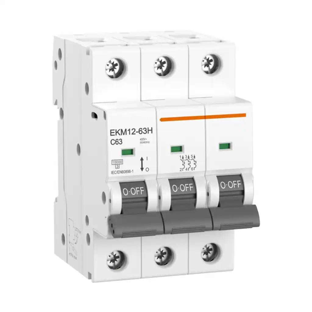
These photos show pole count only. They do not prove that a particular model is approved for a single-phase connection, that all poles have identical sensing, or that it is compatible with a particular panel.
UL Solutions gives a clear rule for North American molded-case breakers. Three-pole breakers are normally for three-phase systems unless they carry a marking that permits single-phase use. The marking may specify “outside poles,” “any two poles,” or an equivalent model-specific instruction.[1]
Schneider Electric gives the same practical distinction for its relevant MCCB families. A 3P breaker may use two poles on a three-phase system. Use on a one-phase system depends on the breaker’s actual marking. Its guidance lists some frames that allow single-phase use and others that do not.[2]
If the label or current manual does not clearly authorize the proposed arrangement, treat the answer as not yet approved. Ask the manufacturer or specify a purpose-built 2P breaker.
This can be a valid use when the load is connected between two phase conductors. The voltage between them must fit the breaker rating. The chosen two poles must be permitted, and the panelboard and local rules must allow the installation. The third pole is unused only as documented.
This needs clear product evidence. One three-pole model may be marked for single-phase duty. Another model from the same brand may be restricted to three-phase use. Do not copy a connection from a similar frame. Use the exact catalog number, label and current installation manual.
Product standards help define the context, but they do not replace the model instructions. IEC 60947-2:2024 covers low-voltage circuit breakers intended for operation by instructed or skilled people within its stated voltage scope.[5] IEC 60898-1 addresses AC overcurrent breakers for household and similar installations.[6] The device marking and accepted installation rules for the destination market still control.
Two independent two-pole circuits require four current paths. Circuit A needs two, and Circuit B needs two. An ordinary three-pole breaker has only three paths. Those paths normally share one operating and trip mechanism.
Potentially acceptable: only when this exact pole pair and unused-pole treatment are documented.
Not a substitute: Circuit B is missing a fourth path, and both circuits would be tied to one common operation.
Do not share a pole between unrelated circuits, route a neutral through an arbitrary phase pole, or use the unused pole as a “spare” independent breaker. Engineered multiwire circuits and listed distribution assemblies have their own conductor, neutral and disconnect rules; they are not created by improvising with a 3P device.
Use this sequence for design review, model matching or an RFQ. If a step is unknown, stop and obtain the missing evidence.
State AC or DC, supply voltage, phase arrangement, grounded or neutral conductors, one load or multiple circuits, design current and load type.
Record manufacturer, full catalog number, poles, protected poles, trip unit, rated current, voltage, frequency, curve or settings and accessories.
Look for “any two poles,” “outside poles,” a defined current path, a single-phase rating or another explicit diagram. Never choose the pair by convenience.
Check voltage between conductors and to ground, straight versus slash rating where relevant, AC/DC duty, prospective fault current and the stated breaking capacity at that voltage.
Confirm conductor protection, load inrush, thermal and magnetic response, common trip, sensing, neutral treatment and any residual-current or ground-fault function.
Check the panelboard label, approved breaker family, bus and main kit, terminal capacity, torque, enclosure, cover, accessories, coordination and destination-market requirements.
A 400/415 V label does not mean a breaker can be used in every 230 V arrangement. A slash-rated breaker also has a conductor-to-ground limit. UL Solutions explains why straight and slash voltage ratings are applied differently.[1]
Do not assume a three-phase time-current curve stays unchanged when only one or two poles carry current. Schneider Electric’s current ComPacT NSXm guidance gives a model-specific example. When loaded single phase, its bimetallic thermal protection can trip more slowly than the published three-phase curve.[4] This is not a rule for every breaker. It is a reason to obtain the correct curve for the actual application.
For practical product selection, compare the required duty with the relevant SENTOP miniature circuit breaker or molded case circuit breaker range. If you are not sure which category fits, review the MCB vs MCCB guide before requesting a model.
This tool does not approve wiring. It tells you whether the basic evidence is complete enough for a qualified review.
Select Yes only when you have a label, manual, calculation or assembly document that supports it.
Some motor protection breakers need current through all three poles. A manufacturer may require two poles in series for single-phase use. Never copy this method to a normal MCB.
Metering, neutral sensing, ground-fault functions and accessory power can depend on the exact pole arrangement. Obtain the trip-unit diagram and test procedure.
DC arc interruption can require a stated polarity and poles in series. Use only a breaker with the required DC marking and manufacturer connection diagram.
Schneider Electric’s GV motor-protection guidance requires a specific single-phase series connection so all three poles carry current.[7] The lesson is to follow the exact device diagram—not to loop conductors through an ordinary breaker without authorization.
For a faster and safer model review, include enough information to confirm the exact approved configuration:

Sometimes. The exact breaker must permit the proposed two-pole use, the approved pole pair must be used, and the voltage, trip behavior, breaking capacity and panelboard compatibility must all fit the circuit.
Only when the exact breaker is marked or documented for that single-phase connection. Do not assume approval from the brand, case size or a similar product family.
No, not as a substitute for two independent protective devices. Two separate two-pole circuits need four current paths and the correct protection and disconnection arrangement.
Use only the pair named in the manufacturer’s instructions for the exact model. It may be any two poles, the two outside poles or a defined current path. If the manual is silent, do not choose a pair yourself.
Not by default. The pole shares the breaker’s common operating mechanism and is not an independent protective device. Use a dedicated breaker unless the complete assembly documentation explicitly provides another approved arrangement.
Only if the exact breaker has the required DC rating and a manufacturer diagram for that voltage, polarity and series-pole connection. AC and DC interruption duties are not interchangeable.
Safety notice: This guide supports selection and technical discussion; it is not a field wiring instruction or an approval for a specific installation. Electrical work must follow the current product instructions, panelboard documentation and applicable rules. De-energize, lock or tag as required, verify the de-energized state, and use qualified electrical personnel.[8]
When the documentation is missing or the application is unusual, the practical answer is simple: use a purpose-designed 2P breaker or obtain written confirmation from the breaker and assembly manufacturer.
Send SENTOP the circuit topology, voltage, current, pole requirement, fault level, target standard, panel information, quantity and destination. Model availability and documentation are confirmed against the exact requirement.
