
Module/string to controller
Start with module Isc, string topology, the applicable PV calculation, the maximum series-fuse rating and the PV conductor.

There is no universal fuse size for every 200 W panel. A 15 A gPV fuse can be correct for some module strings, but the decision starts with the protected circuit, the module's Isc and maximum series-fuse rating, the number of parallel strings, the conductor, the DC voltage and the equipment manual.
A small solar system contains several electrical paths. The panel-to-controller path is not the same as the controller-to-battery path. If the system also has an inverter, its battery cable is a third path with a much higher possible current.
For a PV string, a 15 A gPV fuse may be suitable when the exact Isc calculation, module maximum series-fuse rating, cable, holder, maximum DC voltage and local rule all agree. The same 15 A value should not be copied to the battery or inverter cable.
One 200 W module may not need a string fuse for reverse-current protection in every design. Parallel strings change the fault path because healthy strings can feed current backward into a faulted string. Local rules and the module instructions decide what protection is required.
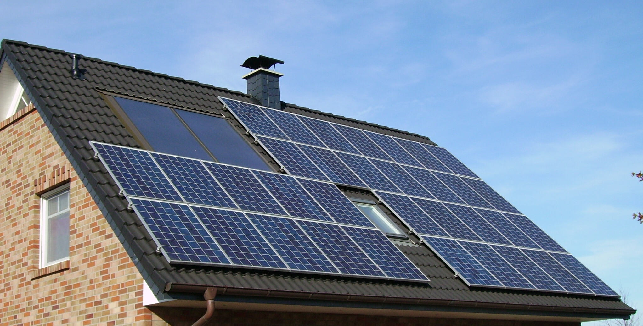
Start with module Isc, string topology, the applicable PV calculation, the maximum series-fuse rating and the PV conductor.
Use total parallel-string current, the output conductor, controller input limits, combiner data and the full DC fault duty.
Follow the controller's specified battery-fuse range and coordinate it with the battery cable, terminals and battery system.
Use the inverter input, battery voltage, surge duty, conductor and interrupting requirement—not the panel wattage.
Use the exact nameplate or datasheet for the panel revision in front of you. “200 W,” “12 V” and “24 V” product descriptions are not enough.
Isc is the short-circuit current and is a common starting point for PV source/string calculations. Voc is the open-circuit voltage and helps establish the maximum cold-condition circuit voltage. Imp and Vmp describe the maximum-power operating point, but they do not replace Isc when the required method calls for Isc.
The maximum series-fuse rating is an upper boundary set by the module manufacturer. It does not tell you that a fuse is always needed, and it does not tell you the fuse size for a controller-to-battery or inverter circuit.
A “12 V” battery system may use a panel with Vmp near 20 V or more. An MPPT controller also changes the voltage-current relationship between its PV input and battery output.

This example explains the decision path. It is not a design approval or a substitute for the current code, authority having jurisdiction or equipment instructions.
| Official product example | Published electrical data | What the data proves |
|---|---|---|
| Renogy 16BB N-Type 200 W, 24 V product | Vmp 31.03 V; Imp 6.46 A; Voc 37.44 V; Isc 6.85 A; maximum series fuse 15 A | A 15 A number is a module boundary. It does not mean every 200 W circuit needs a 15 A fuse. |
| Canadian Solar CS6A-200M example | Vmp 24.3 V; Imp 8.22 A; Voc 30.0 V; Isc 8.74 A; maximum series fuse 15 A | The same 200 W label can come with a different Isc and voltage. The exact module data matters. |
| Victron MPPT 100/20 controller example | 20 A maximum battery current; 290 W nominal PV power at 12 V; 25–30 A battery-fuse range | The controller-to-battery fuse can be larger than a PV string fuse because it protects a different circuit. |
There is no universal yes-or-no answer. The key question is whether another source can drive damaging reverse current into a faulted module or conductor.

With no parallel string, there may be no bank of healthy strings available to force substantial reverse current into a faulted string. A string fuse may therefore be unnecessary for that specific protection purpose. Yet conductor protection, isolation, controller instructions or local rules can still require another device or arrangement.
Series wiring raises voltage while the string current stays near one module's current. Do not double the fuse ampere rating just because there are two panels. Recheck the cold-corrected total Voc against the controller, fuse holder and isolator voltage ratings.
Parallel wiring increases available current. If one string faults, healthy strings can feed current backward into it. The module manual, number of strings, Isc, maximum series-fuse rating, conductor and local rule determine whether each string needs certified protection.
Review the module and controller manuals, cable path, service isolation and local rules. Do not install a random inline fuse only because a kit includes one.
Use string Isc for current logic and cold-corrected total Voc for the DC voltage check.
Recalculate string protection, combined output conductors, combiner components and controller input limits.
A combiner box brings several PV strings into one output. A string fuse, combined-output fuse or breaker and disconnect can each protect or isolate a different part of that system. One device does not automatically replace the others.
The selected assembly must coordinate with the maximum string and combined current, maximum circuit voltage, prospective fault duty, conductor sizes, terminals, enclosure temperature, environmental exposure and the controller or inverter input.
It limits the permitted series protective device for the module. It does not set the rating of the combiner output conductor, controller battery cable or inverter lead.

An MPPT controller can convert higher PV voltage and lower PV current into lower battery voltage and higher charging current. The battery also has much greater fault-current capability than one module.
Use Isc, Voc, topology, module limits and the adopted PV method.
PV STRING OCPD — IF REQUIREDPV input limits and battery output limits are separate specifications.
FOLLOW THE EXACT MANUALPlace the prescribed protection to limit battery-fed fault energy in the cable and equipment.
BATTERY-SIDE FUSESize each branch from its load, cable, surge duty and equipment instructions.
SEPARATE BRANCH PROTECTION
The official manual lists a maximum battery current of 20 A, nominal PV power of 290 W at 12 V and a 25–30 A battery-fuse range for this controller.
This does not prescribe a 25 A or 30 A fuse for every 200 W system. It proves that the controller-to-battery decision comes from the controller and battery-side conductor—not the module's 15 A maximum series-fuse value.
Battery-to-inverter protection is different again. A 1,000 W inverter at a nominal 12 V can draw about 83 A before losses at rated output. That arithmetic shows scale only; the actual fuse comes from the inverter, battery, cable and approved design.
Fuse link, holder, enclosure, conductor and isolation method must work together at the real DC voltage and fault duty.
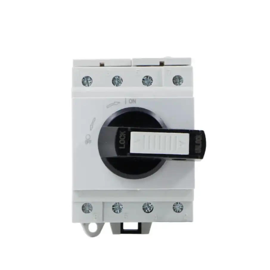
Use the applicable current calculation and standard size while staying within the module, conductor, terminal and equipment limits.
The fuse and holder must cover the maximum circuit voltage, including cold-corrected PV string Voc. Nominal battery voltage is not the PV voltage-rating requirement.
The assembly must safely interrupt the available fault current at its installation point. Battery circuits and PV circuits can need different product classes.
For PV strings and arrays, use a fuse link and holder documented for that PV duty, such as the required gPV solution. Check enclosure IP, UV, temperature, terminals, conductor range and touch protection.
Review SENTOP DC isolator options for a coordinated renewable-energy BOM.
Confirm both parts have compatible current, DC voltage, PV application and breaking capability.
The protective device must protect the cable after temperature, grouping, enclosure and installation corrections.
A fuse holder is not automatically a load-break switch. Use a correctly rated DC isolator where required.
Overcurrent protection does not replace properly selected surge protection, earthing or other required safeguards.
Use this sequence for a new system, a product quote or a design review. Stop if the protected location or source data is unknown.
Choose PV string, combined PV output, controller-to-battery, battery-to-inverter or a separate DC branch on the one-line diagram.
Record module part and revision, Isc, Imp, Voc, Vmp, maximum series fuse, controller, battery, inverter, cable, holder and enclosure.
Count modules per string and strings in parallel. Identify every source that can feed a fault, including the battery and DC bus.
Use the adopted code or standard for the PV circuit. Follow controller, battery and inverter manuals for their respective circuits.
Carry expected current without nuisance opening while protecting the conductor and staying within the module and equipment limits.
Check cold-corrected Voc or battery voltage, breaking capacity, pole conditions, holder and enclosure ratings.
Check terminals, torque, thermal conditions, IP/UV exposure, labels and test records. Control substitutions after approval.
Use the approved isolation, connection, inspection and commissioning process. Never work live or use a fuse holder as an unapproved switch.
| Observed problem | Likely reason | Correct response |
|---|---|---|
| 15 A fuse opens on the battery lead | The module's maximum series-fuse value was copied to the controller-to-battery circuit. | Stop resetting it. Read the controller manual and recheck the battery cable, battery source and device class. |
| Fuse holder becomes hot or discolored | Loose termination, unsuitable holder, undersized cable or enclosure heat. | De-energize by the approved method and have the entire assembly inspected and corrected. |
| Fuse opens after adding parallel panels | Array current and reverse-feed paths changed without a new design review. | Update the one-line diagram, Isc calculation, combiner, conductors, holder and controller input check. |
| Device says 15 A but only 32 V automotive | The ampere number matches, but the DC voltage and PV interruption duty do not. | Use a documented PV/DC fuse-and-holder assembly for the real maximum voltage and fault duty. |
| Fuse holder used as a daily switch | The holder may not be load-break rated. | Use the specified DC-rated isolator and follow its operating procedure. |
| Design starts with 200 W ÷ 12 V | Battery nominal voltage was confused with PV Vmp/Voc and controller conversion. | Calculate each circuit from the data at that circuit location. |
A part can be recommended only after the protected path, electrical limits and target market are clear. Send the following data with your BOM or one-line diagram.
These answers are planning guidance. Final selection depends on the exact product documents, circuit design and rules adopted where the system is installed.
Sometimes, but not automatically. A 15 A gPV string fuse can be valid when the module Isc calculation, local method, conductor and the module's maximum series-fuse rating support it. It is not a general answer for every 200 W panel, and it is usually not the battery or inverter fuse.
Not always for reverse-current protection. One un-paralleled module has a different fault path from several parallel strings. Still check local rules, conductor protection, service isolation and the controller and module instructions before deciding that no PV-side device is needed.
In a normal MPPT or PWM system, separate the PV-to-controller circuit from the controller-to-battery circuit. The battery-side fuse follows the controller manual, battery cable, battery fault source and local requirements—not the panel's maximum series-fuse rating.
An MPPT controller can convert higher PV voltage into lower battery voltage and higher charging current. For example, Victron specifies a 25–30 A battery-fuse range for its MPPT 100/20. That is a controller-specific example, not a universal value.
Not from wattage alone. A 20 A string fuse would exceed the 15 A maximum series-fuse rating of the two 200 W module examples in this guide. A 20 A device may fit another module or a different circuit only when all current, voltage, conductor, equipment and code limits permit it.
Voltage rises while string current remains near one module's current. Recheck cold-corrected total Voc against the controller, fuse holder and isolator voltage ratings. Do not double the string-fuse ampere rating merely because there are two panels.
Available current rises while voltage stays near one string's voltage. Recalculate the combined output conductor and review reverse-current protection for each string. The exact module manual and local rule decide whether individual string fuses are required.
Do not assume so. A PV circuit needs a fuse link and holder with the correct DC voltage, PV application and breaking capability. A low-voltage automotive fuse can have the right ampere number but the wrong voltage and interruption duty.
Either can be appropriate only when it is specifically rated and applied for the circuit. A PV fuse is a one-time overcurrent device. A PV/DC breaker may add resettable protection and possibly switching, but its voltage, breaking capacity, pole configuration and manufacturer markings must fit the design.
These sources support the examples. They do not replace the current adopted rules, authority having jurisdiction or exact equipment instructions for a project.
Send the protected circuit, module and equipment models, series/parallel layout, current, maximum DC voltage, cable and terminal data, environment, target market and required certification. SENTOP can help organize a coordinated product and BOM discussion.
