
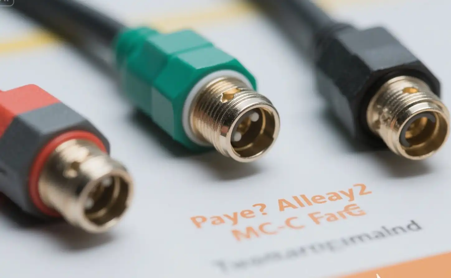
Are All MC4 Connectors the Same?
No. A 4 mm PV connector that clicks into another connector is not automatically an approved electrical, environmental, or certification match. Use the exact mating pair named by the module, inverter, and connector manufacturers. Cross-mate brands only when that precise combination is listed or jointly evaluated for intermatability and the applicable instructions identify it.
SENTOP editorial image. Product appearance is illustrative; it does not prove cross-brand compatibility or certification.
Do these two connectors belong together?
Do not start with shell shape. Start with the two exact part numbers and their documentation. If any answer is unknown, stop and identify the connection before mating or energizing it.
Exact approved pair
Both part numbers appear in the manufacturer’s mating table, equipment instructions, or applicable listing evidence. Continue with the approved cable and tools.
Different family or revision
Do not assume. A manufacturer can sell several similar families with different contacts, seals, or mating correlations.
“MC4 compatible” claim only
Do not mate on marketing language alone. Require evidence for that exact cross-brand combination, not two separate certificates.
Replace the complete pair
If the counterpart cannot be identified or has heat, water, corrosion, or mechanical damage, isolate the circuit and replace the matched pair as the OEM directs.

A click proves engagement—not compatibility
“MC4” is a protected Stäubli trademark for a 4 mm photovoltaic connector system. The market also uses the term loosely for many look-alike 4 mm PV connectors. Those products may share a familiar locking shape, yet use different contact springs, plating, seal dimensions, materials, or manufacturing tolerances.
That difference may not be obvious during installation. A mixed pair can feel firm and still produce higher resistance, weaker sealing, or uneven contact pressure after heat cycles and outdoor exposure. The safer description for a non-Stäubli product is 4 mm PV connector plus its manufacturer, family, and part number.
Ask: compatible with which exact plug, socket, cable, termination method, standard, and rating? A broad claim cannot replace a model-level certificate, mating-correlation table, or equipment instruction.
- Same manufacturer: still verify the exact product family and mating table.
- Different manufacturers: use only if the precise combination is evaluated or listed for intermatability and both instructions permit it.
- Unknown installed half: do not add one new half and hope; identify it or replace the complete pair.
The nine items that must agree
Connector compatibility is a system decision. Check every layer below before approving a new purchase, replacement lead, branch adapter, or field termination.
Manufacturer and exact family
Record the maker, model family, both mating part numbers, revision, and any molded identifier. Similar logos or black housings are not enough.
Evidence: model datasheet + mating tableEquipment permission
Check the module, inverter, MLPE, combiner, or junction-box instructions. Factory leads can be tied to a listing, warranty, or approved replacement process.
Evidence: equipment installation manualContact and housing pair
The metal contact, spring design, housing key, latch, and seal must belong to the documented pair. Housing fit alone cannot confirm the internal interface.
Evidence: assembly drawing + part correlationCable construction
Verify conductor cross-section or AWG, cable outer diameter, strand class and count, conductor material or plating, insulation, and applicable PV cable standard.
Evidence: connector cable matrixVoltage and current
Use the exact product rating. Compare it with calculated maximum DC voltage, design current, cable ampacity, temperature, and required code factors.
Evidence: certificate + project calculationTemperature and environment
Check ambient limits, UV, moisture, chemicals, salt, ammonia, elevation, water routing, and mechanical stress. Do not turn one IP code into an all-weather promise.
Evidence: environmental ratings and test scopeApproved tools and torque
For crimp types, match the strip length, contact, locator, die, crimper, gland tool, and product-specific torque. “MC4 tool” is too vague.
Evidence: current assembly instructionsCertification scope
Verify the active certificate in the issuing body’s database. The record must cover the exact model, counterpart, cable, termination, and ratings.
Evidence: certificate number + database statusComplete lead and system
An extension, adapter, or branch lead is limited by its lowest-rated connector, cable, splice, and downstream equipment. Review the entire current path.
Evidence: BOM + single-line diagramWhat can happen inside a mismatched joint
A connector can pass a quick visual check and still deteriorate. The path below explains why documentation and assembly control matter.
Small interface mismatch
Different contact shapes, spring forces, plating, or seal dimensions create an interface the two products were not evaluated to share.
The latch may still close.Resistance or sealing weakness
Incomplete contact, a poor crimp, contamination, or seal compression outside its design can raise resistance or admit moisture.
The defect may be hidden.Heat and thermal cycling
Current through higher resistance creates local I²R heating. Repeated hot-cold cycles can further change contact pressure and materials.
Load and ambient conditions matter.Corrosion or material damage
Moisture, oxygen, contamination, UV, cable movement, and incompatible materials can worsen the joint over time.
An IP label is not a cure.Power loss, arcing, or fire risk
Severe deterioration may produce overheating, insulation damage, ground faults, or arcing. Stop and replace damaged parts; do not “clean and reuse.”
Investigate the root cause.What does—and does not—prove a match
Use this table during supplier review. It turns vague claims into evidence a buyer or engineer can actually check.
| Claim or observation | Why it is insufficient | What to request instead |
|---|---|---|
| “It clicks together” | Mechanical engagement only. It says nothing about contact force, sealing, material compatibility, or certification. | Both exact part numbers in a mating-correlation table or equipment instruction. |
| “Both are MC4 compatible” | The phrase has no single universal certification meaning and may describe appearance rather than an evaluated pair. | Model-level certificate, exact counterpart, cable range, ratings, and written intermatability evidence. |
| “They are the same brand” | One manufacturer may have several generations or families that are not intended to mate. | Exact family/revision plus current assembly instructions. |
| “Both are 1500 V / 30 A” | Equal headline ratings do not make interfaces compatible. Current also depends on cable and temperature. | Exact pair rating under stated conductor and environmental conditions. |
| “Both carry IEC or TÜV marks” | Separate product certificates do not automatically evaluate the mixed pair. IEC publishes standards; a certifier evaluates named products. | Active database record whose scope covers the actual pair and use. |
| “Both are IP67 or IP68” | IP applies to a tested configuration and state. It does not prove cross-mating or permanent immersion suitability. | Mated and unmated ingress ratings, sealing-cap requirements, and installation limits. |
| “The cable is 4 mm” | “4 mm connector” and 4 mm² conductor are different ideas. Cable OD, strands, material, and insulation also matter. | Connector cable matrix listing cross-section/AWG, OD, strand construction, and cable standard. |
Identify an installed connector in eight steps
This is a documentation workflow, not a live-work procedure. PV conductors can remain energized in daylight. Isolation, testing, assembly, mating, and replacement are qualified-person tasks.
Make the work electrically safe
Follow the project’s PV isolation and verification procedure. Identify every source and stored-energy path. Never disconnect a typical PV connector under load.
Stop if the circuit state is not proven.Photograph before disturbing
Capture the full connection, cable routing, module or equipment label, molded marks, polarity marks, and nearby connector pairs.
Preserve the as-found record.Read molded identifiers
Record manufacturer, logo, family, part number, voltage, current, cable range, polarity symbols, certification marks, and production codes.
Use a light and magnification if needed.Trace the factory lead
Identify the module, inverter, optimizer, combiner, or junction box that supplied the lead. Find its current installation manual.
Equipment instructions can control the pair.Verify both halves
Do not identify only the new replacement. Confirm the installed counterpart’s exact make, family, condition, and permitted mate.
Two known halves make one decision.Check cable and tooling
Compare the actual cable marking and OD with the connector matrix. Confirm contact, strip length, die, locator, crimper, gland tool, and torque.
A connector body alone is not the assembly.Validate certification
Look up the certificate number in the certifier’s database. Check model, counterpart, cable, factory/status, ratings, and conditions—not just a logo.
Save the controlled evidence.Record the approved combination
Update the BOM, string map, inspection record, replacement kit, and approved-tool list so the next technician does not have to guess.
Traceability prevents future cross-mating.
The module or equipment manual can decide the connector
A replacement should not begin with “which connector looks right?” Begin with the module, inverter, optimizer, combiner, or junction-box documentation. The original lead may be part of a certified configuration, and changing one half can affect the conditions under which the equipment was evaluated.
If the factory connector is damaged, follow the equipment manufacturer’s approved repair or replacement method. Do not open, splice, shorten, or change a factory lead merely because a similar connector is available. Also check warranty terms and local inspection requirements.
Use the same approved make and type for the complete mated pair. If a cross-brand transition is unavoidable, require precise listing or joint-evaluation evidence for that pair and written permission in the relevant instructions. If neither is available, redesign the transition with an approved matched family.
- Do not infer polarity from the outer housing shape; verify markings, drawings, and polarity through the approved commissioning procedure.
- Cap unmated ends with the manufacturer’s sealing caps and keep contacts clean and dry.
- Route cable to avoid standing water, tight bends, pull, twist, and connector weight hanging from the lead.
Cable preparation and tools are part of the connector
A genuine housing can still fail when assembled with the wrong cable, contact, die, strip length, or gland torque. “Tool-free” products are model-specific exceptions, not a rule for PV connectors.


Match and strip the cable
Confirm conductor cross-section, cable OD, strand construction, conductor material, insulation, and strip length. Do not cut strands or tin them unless expressly permitted.
“4 mm connector” does not mean any 4 mm² cable fits.Use the approved contact and die
Use the exact contact, locator, die, and calibrated crimp tool assigned to the connector-and-cable combination. Inspect the crimp as the current instructions require.
A generic crimper can create a hidden high-resistance joint.Seat, seal, and torque
Confirm the contact is fully locked in the housing. Position the seal correctly and tighten the cable gland to the model-specific value and method.
Do not apply a universal MC4 torque.Verify full engagement
Keep contacts clean and dry. Mate only the approved pair, confirm the latch exactly as instructed, protect cable from strain, and complete the documented inspection.
Never disconnect a typical PV connector under load.PV modules can energize conductors whenever illuminated. Only qualified personnel should assemble, mate, disconnect, test, or replace PV connectors using the project’s isolation, verification, PPE, and commissioning procedure.
Straight, branch, extension, and adapter products need different checks
A different shell format does not remove the compatibility rules. Treat every interface and every current path as part of the engineered PV system.
Field-assembled or factory lead
This is the familiar single-pole plug/socket connection. Verify the exact mating pair, cable, contact, tools, ratings, and assembly instructions.
Best for: a documented one-to-one DC connection.Parallel connection component
A branch changes the current path. Check combined current, conductor and connector ratings, inverter input limits, module maximum-series-fuse data, and required overcurrent protection.
It is not a general “easy expansion” accessory.Preterminated cable assembly
Verify both end pairs, cable standard and size, voltage drop, outdoor routing, length, strain, and the lowest rating in the complete lead.
Unknown preterminated ends are not automatically compatible.Two interfaces, two approvals
Do not use an adapter simply to force unlike shells together. Each side must be a documented approved pair, and the complete transition must meet system ratings and equipment instructions.
When evidence is missing, use one matched family instead.Module bypass diodes, blocking diodes, string fuses, and reverse-current protection perform different jobs. An in-line diode is not a universal fix for shade or a safe add-on merely because its housings can mate. Select it only through the PV array design.
Keep, replace the pair, or escalate?
Do not “repair” a burned, cracked, wet, corroded, or deformed connector. Isolate the circuit, document the condition, investigate the cause, and follow the equipment and connector manufacturers’ replacement instructions.
Only when identity and condition are proven
Qualified-person inspection confirms the exact approved pair, proper engagement, correct cable and assembly, clean/dry condition, acceptable routing, and no thermal or mechanical damage.
- Part numbers recorded
- Certificate/instructions current
- No cross-mating or unknown repair history
- Inspection result entered in asset records
When one half or its history is uncertain
Replace both mating halves when the counterpart cannot be identified, an unapproved cross-mate is found, or heat, corrosion, contamination, water entry, latch damage, seal damage, or poor field termination is present.
- Remove heat-affected cable as directed
- Use one approved make/type pair
- Use its approved cable and tools
- Correct routing and environmental cause
When the change affects the system
Escalate factory-lead modifications, mixed equipment, uncertain listings, branch-current changes, adapters, repeated heating, ground-fault evidence, widespread unknown connectors, or any proposed deviation from instructions.
- Module/inverter/MLPE approval
- Code and AHJ review where required
- Protection and current-path calculation
- Documented commissioning plan

Do not blame the connector body alone
Local heating can come from a poor crimp, wrong contact, incomplete insertion, contamination, corrosion, mechanical load, excessive current, wrong cable, or an unapproved pair. The corrective action must address the full connection and its operating conditions.
- Record load, ambient conditions, location, cable, part numbers, and the as-found connection.
- Check adjacent connectors from the same installation batch and tool process.
- Do not sand, bend, clean, or re-use damaged contacts or housings.
- After replacement, complete the inspection and commissioning tests required by the equipment design and project rules.
What IEC, UL, IP, and TÜV do—and do not—prove
A standard defines technical requirements. A certification record covers named products and conditions. Neither replaces correct pair selection or field assembly.
| Reference | Useful scope | Buyer boundary |
|---|---|---|
| IEC 62852:2014+A1:2020 | Product safety and test requirements for PV DC connectors within its stated scope. | The standard’s scope ceiling is not a universal product rating. Verify the exact certified model, pair, cable, and conditions. |
| IEC TR 63225:2019 | Technical report addressing incompatibility of PV DC connectors made by different manufacturers. | Use it to understand the cross-mating risk; use product/equipment evidence to approve the actual pair. |
| IEC 62548-1:2023 | PV array design requirements, including the connector within the larger DC design. | Array design and connector product certification are different layers. Apply the current adopted project requirements. |
| UL 6703 / UL 6703A | North American PV connector and combination evaluation paths, depending on product and application. | UL 6703’s intermatability route is exact-combination evidence—not permission to mix any two separately certified products. |
| IEC 60529 IP Code | Ingress-protection classification for the tested enclosure/configuration. | State mated/unmated condition and test limits. IP is not cross-mating certification, chemical resistance, or a permanent-immersion promise. |
| TÜV certificate or mark | Evidence from a conformity-assessment body for the products, standard, factory, and conditions shown in its record. | Verify the certificate number and current status in the issuing body’s database. A logo alone is not enough. |
| IEC 62446-1 | PV system documentation, commissioning tests, and inspection. | It is not the product-certification standard for MC4-style connectors. Do not use it as a connector-model approval. |
| NEC-based projects | The adopted electrical code and authority having jurisdiction govern the installation. | Confirm the edition adopted locally and its PV mating-connector requirements; do not export one NEC edition as a global rule. |
For UL evidence, use UL Product iQ. For TÜV Rheinland evidence, use Certipedia. Match the exact model, counterpart, cable/termination, rating, status, and conditions to the item being ordered.
Send model evidence—not “MC4 connector required”
A useful RFQ identifies the complete PV connection, destination market, equipment, cable, current path, environment, certificates, assembly process, and inspection evidence. SENTOP can help organize the wider solar DC BOM and documentation; final connector approval remains with the applicable equipment and connector manufacturers, project engineer, and local requirements.
Related SENTOP solar and protection resources
Connector selection is only one part of the PV DC system. Continue with isolation, surge protection, combiner wiring, standards evidence, and project-level component matching.
Solar & Energy Systems
See SENTOP’s B2B electrical-component path for solar system suppliers and project contractors.
DC isolationDC Isolator Switches
Review the isolation component as part of the complete photovoltaic DC architecture.
Overvoltage protectionSurge Protective Devices
Match surge protection to the DC system, earthing design, voltage, and application requirements.
Wiring guideWire Panels Into a Combiner Box
Continue from connector identity to string routing, current paths, protection, and combiner documentation.
Risk controlPrevent Rooftop PV DC Arc Faults
Understand how connection quality, wiring control, protection, and maintenance work together.
EvidenceStandards & Certificates
Request current, model-specific documentation instead of relying on a product-page badge.
MC4 connector compatibility FAQ
These short answers support quick decisions. Use the main checklist whenever you approve a real model or repair.
Are all MC4 connectors interchangeable?
No. Many 4 mm PV connectors look similar, but physical fit does not prove electrical, environmental, or certification compatibility. Use the exact pair documented by the connector and equipment manufacturers.
Can I connect two different MC4 brands?
Only when that precise cross-brand combination is jointly evaluated or listed for intermatability and is explicitly identified in the applicable manufacturer and equipment instructions. Two separate product certificates are not enough.
Are two connectors from the same manufacturer always compatible?
No. A manufacturer may offer several families or revisions with different contacts, seals, keys, tools, and ratings. Verify the exact family and both mating part numbers.
What does “MC4 compatible” mean?
There is no single universal approval behind that phrase. Treat it as a marketing claim until the supplier provides exact model-level pairing, certificate, cable, tool, rating, and instruction evidence.
What does MC4 mean?
MC4 is a protected Stäubli trademark for its 4 mm PV connector system. It is not the name of one universal connector standard. Other products are better identified as 4 mm PV connectors with their exact maker, family, and part number.
Do MC4-style connectors need special tools?
Most crimp-type models require the contact, strip length, locator, die, crimp tool, gland tool, and torque specified for that connector and cable. Tool-free models exist, but they are model-specific exceptions.
Does IP67 or IP68 mean a connector is waterproof?
It describes ingress performance for a tested configuration and condition, often when correctly assembled, locked, and mated. It does not automatically allow permanent immersion, standing water, direct burial, chemicals, or an unmated open end.
Can I disconnect an MC4-style connector under load?
Typical PV connectors must not be disconnected under load. PV conductors may remain energized in daylight. Qualified personnel must follow the system-specific isolation and verification procedure and the exact product instructions.
Can I replace only the damaged half?
Only if the remaining half’s exact identity, approved mate, and undamaged condition are proven and the equipment instructions permit it. If identity or condition is uncertain, replace the complete matched pair and any heat-affected cable as directed.
Standards and technical evidence used
Standards and product instructions change. Confirm the edition adopted by the project and the current controlled document for the exact connector.
Approve the pair, cable, tools, and system—not the shape
Send SENTOP your destination market, solar DC single-line diagram, equipment list, connector part numbers, cable data, and protection requirements for a clearer project-level BOM discussion.
