
Clears the overcurrent
Its element melts when current and time exceed its designed response. Its voltage rating, breaking capacity and time-current curve control whether it can interrupt the fault safely.

A fuse holder supports a replaceable fuse and connects it into the circuit. It provides contacts, terminals, insulation and retention; the fuse supplies the calibrated overcurrent protection. Choose the exact fuse first, then match the holder’s format, AC or DC voltage, usable current, fault duty, temperature, terminals, access protection and certification.
Photo: Dmitry G / Wikimedia Commons, CC BY-SA 3.0.
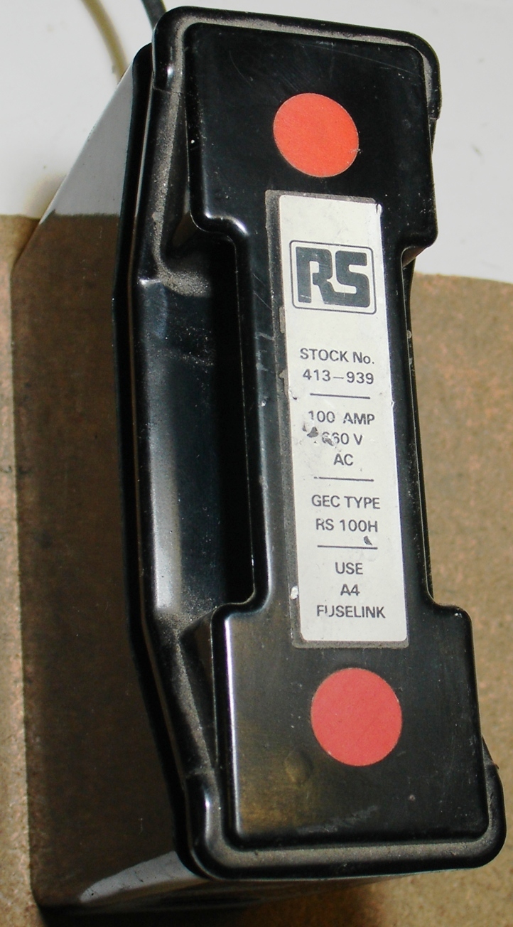
A fuse holder is the mechanical, electrical and insulating interface between a replaceable fuse and the rest of a circuit. It brings current into one end of the fuse and out of the other, holds the fuse in the correct position, and may add a carrier, cap, cover, indicator or touch-safe barrier.
The holder does not decide when the circuit opens. The fuse element does that according to its time-current curve and breaking capacity. A holder also cannot make an incorrect fuse safe. If the size, voltage, heat loss or fault duty is wrong, physical fit is not enough.
Define the protection job, select the exact fuse, and then select a holder approved for that fuse family and for the real installation conditions. Validate the pair in the equipment before production release.
Its element melts when current and time exceed its designed response. Its voltage rating, breaking capacity and time-current curve control whether it can interrupt the fault safely.
Its contacts and terminals carry normal current. Its body retains the fuse and separates live parts. Its thermal, mechanical and certification limits remain part of the protection system.
The path is simple, but every joint must stay tight, cool and insulated. Contact condition matters during normal operation, while the fuse must handle the actual overcurrent event.
The source conductor, PCB trace or busbar enters the holder.
A clip, blade, cap or stud transfers current into the fuse.
The calibrated element carries normal current and opens on a qualifying overcurrent.
The opposite interface transfers current out of the fuse.
The protected circuit continues to the connected equipment.

Supports conductive parts and provides the required insulation, creepage, clearance and mounting geometry.
Grip or bolt to the fuse ends. Weak spring force, oxidation or loose hardware raises resistance and temperature.
Connect wire, busbar or PCB copper. Conductor range, crimp quality, strip length and torque must match the data sheet.
Positions the fuse and may allow service from outside an enclosure. It is not automatically rated to switch a load.
Restricts accidental contact and may be part of a finger-safe or IP-rated assembly when installed exactly as tested.
Can report an open fuse, but its voltage, polarity and leakage path are model-specific. It is never proof of zero voltage.
The correct form depends on where the fuse is mounted, who will replace it, how the surrounding enclosure protects people, and how much current and fault energy the assembly must handle.


A low-cost choice inside a closed enclosure. The PCB, solder joints and enclosure must provide spacing, retention and access control.
Provides better retention around a miniature cartridge fuse, but board temperature, trace width, solder process and service access still limit use.
Supports front or rear access in appliances, power supplies and instruments. Check panel cutout, cap, rear-terminal barriers and shock-protection category.
Fits batteries, vehicles and equipment wiring. Wire gauge, crimp tool, strain relief, sealing, vibration and distance from the source become key controls.
Supports organized installation, labeling and grouped circuits. Confirm fuse class, conductor torque, spacing, ventilation, AC/DC rating, SCCR and switching function.
Common for branch circuits, feeders and machinery. Covers and rejection features can reduce unsafe substitution, but an enclosure is usually still required.
Available in many blade sizes and sealed forms. A 12 V label does not resolve continuous current, heat, vibration or battery fault-current capability.
Used with semiconductor, inverter, drive, UPS and battery fuses. Fuse watts loss, bolt torque, bus geometry, cooling and dynamic forces are design-critical.
Designed around specified gPV fuses and high DC voltage. Check backfeed, polarity, temperature, altitude, conductor, IP condition and exact combination rating.
Holder, block and disconnector are not automatic synonyms. A movable carrier may look like a switch, yet opening under load or using it as the required isolation point is allowed only when the manufacturer and applicable standard state that function.
A holder’s ampere marking is only one input. Build the specification from the exact fuse, circuit, installation and destination-market requirements.
Covers holders for specified miniature fuse-links mainly used indoors in appliances, electronic equipment and component parts. It is not a universal standard for every industrial holder.
Sets general requirements for enclosed current-limiting low-voltage fuses within its stated AC/DC voltage and breaking-capacity scope.
UL Solutions identifies UL 248 as the U.S. fuse-standard family and UL 4248 as the fuseholder family. The exact part and product category still matter.
Common fuse sizes include 5 × 20 mm, 6.3 × 32 mm, 10 × 38 mm, 1/4 × 1-1/4 inch cartridges, automotive Micro/Mini/ATO or ATC/Maxi blades, and industrial Classes CC, J, R, T, NH and PV-specific formats. Similar length or diameter does not make their voltage, breaking capacity, rejection features or certification interchangeable.
Check the drawing for diameter, length, blade width, end caps, tags, knife contacts or studs.
Rejection features help prevent a fuse with the wrong protection characteristics from being installed.
Use fuse and holder data for voltage, current, short-circuit capability and permitted combinations.
Use worst-case fuse watts loss, holder power acceptance and the real local temperature.
Never enlarge a clip, grind a fuse end cap, bypass a rejection feature, wrap a fuse in foil or force the wrong fuse into a carrier. These changes can reduce contact pressure, damage insulation and defeat the intended protection system.
Every clip, crimp, screw and bolted joint has resistance. Heat at that joint grows with the square of current, so a loose or corroded contact becomes much more dangerous as load rises. The simple estimate is:
P = I²RA higher-resistance approved replacement fuse may release more heat at the same operating current.
Low spring force, oxidation, contamination, wear and poor alignment raise contact resistance.
Wrong wire size, poor crimping, damaged threads or incorrect torque creates a hot joint.
The air inside an enclosure can be much warmer than the room and may be heated by nearby components.
Closely packed DIN modules, blocked airflow and small enclosures retain heat.
High continuous current, long duty or the wrong fuse-holder pair can exceed the thermal design.
There is no universal fuse-holder derating percentage. Littelfuse recommends no more than 60% of nominal rating for the holders and UL test context described in its guide, while Eaton discusses a different starting approach for electronic holders. Use the rule for the exact product family and verify the real assembly thermally.
Use this sequence to keep the protection objective, the fuse and the holder connected through engineering, purchasing and production.
Record normal and maximum current, inrush, AC/DC voltage, load type, polarity and prospective fault current.
Choose its time-current behavior, current, voltage, breaking capacity, temperature response and coordination.
Specify exact dimensions, contact style, class or series, rejection feature and permitted replacements.
Select PCB, panel, in-line, DIN, block, automotive, bolted or PV construction from the enclosure and service method.
Verify current, explicit AC/DC voltage, fault duty, fuse watts loss, power acceptance and derating.
Define wire, crimp or torque controls, touch protection, IP condition, environment and access level.
Obtain the data sheet, certificate or database record and all conditions of acceptability for the exact model.
Validate worst-case current, fuse loss, ambient, airflow, grouping and conductors; then control the released BOM and assembly process.
Check mains voltage, breaking capacity, power acceptance behind the panel, shock protection, rear terminals, cutout and exact replacement label.
Check fuse class, SCCR combination, wire and torque, side-by-side temperature and whether a true disconnect function is required.
Check fault-current capability, blade size, continuous current at temperature, wire gauge, crimp, sealing, vibration and source-side placement.
Mersen’s US15M1HEL is a model-specific example: 10 × 85 mm, 1,500 VDC, 32 A maximum and 50 kA DC SCCR. Never transfer those values to a similar-looking holder.
Fuse replacement can expose live terminals and substantial fault energy. Follow the equipment instructions and applicable safe-work rules. OSHA 1910.333 states that exposed live parts generally must be de-energized before work, with defined exceptions, and requires appropriate lockout or tagging and verification for covered work. A blown-fuse indicator, open carrier or low nominal voltage is not proof that the circuit is safe.
Do not keep installing fuses into a damaged holder. Isolate the circuit, replace affected parts as required and correct the cause before return to service.
| Observed symptom | Causes to investigate | Appropriate response |
|---|---|---|
| Brown, melted or carbonized body | Overcurrent, high fuse watts loss, loose contacts, poor terminal, high ambient, undersized conductor or blocked cooling. | De-energize. Replace the damaged holder and fuse, inspect connected conductors and correct the root cause. |
| Dark or pitted fuse end cap | Low contact force, oxidation, contamination, vibration, arcing during insertion or incompatible dimensions. | Replace damaged parts as directed and verify the exact fuse fit, contact system and service procedure. |
| Intermittent power | Weak clips, cracked solder joint, loose crimp or screw, vibration, carrier not seated or fuse damage. | Diagnose the complete current path. Do not bend clips as an improvised production repair. |
| Repeated fuse opening | Real overload or short circuit, inrush mismatch, wrong fuse curve/current, high ambient or equipment failure. | Troubleshoot the circuit first. Never install a higher-current fuse just to stop repeat opening. |
| Cap will not close | Wrong fuse length, damaged thread, deformed carrier, foreign material, misalignment or heat damage. | Stop forcing it. Isolate the equipment and fit only the correct approved parts. |
| Corrosion or moisture | Failed seal, condensation, salt, chemicals, washdown or unsuitable materials. | Correct the ingress and environmental specification, then replace affected parts. |
Current does not resolve voltage, fuse loss, contact heat, enclosure temperature or fault duty.
Use the exact published DC rating and permitted fuse combination.
Load-break and isolation functions must be explicitly documented.
Control the fuse, plating, spring material, terminal hardware, crimp tool, torque and change notification.
A useful RFQ identifies the circuit, the exact fuse and the installation. “30 A fuse holder” is not enough to match a safe, repeatable product.
Use these answers as a starting point, then confirm the exact fuse, holder and equipment instructions.
A fuse holder supports a replaceable fuse and connects it into a circuit. It provides contacts, terminals, insulation, retention and often a carrier, cover, touch protection or indicator. The fuse itself provides the calibrated overcurrent protection.
No. The fuse is the sacrificial protective device that opens during an overcurrent. The holder is the interface that carries current to and from the fuse and keeps it mounted and insulated. Both must be correctly rated and compatible.
Yes. A holder’s maximum current can be higher than the selected fuse rating. The design must still confirm fuse watts loss, holder power acceptance, ambient temperature, contact heating and all required derating.
Possibly, but voltage alone is not enough. Confirm AC or DC suitability, current, fuse format, fault current, temperature, terminals and environment. A 12 V battery can still deliver very high fault current.
Only when the manufacturer publishes a suitable DC rating for the exact holder and permitted fuse combination. Do not assume a 250 VAC rating equals 250 VDC.
Common causes include fuse watts loss, high contact resistance, weak or corroded clips, loose terminals, poor crimps, undersized conductors, high current, high ambient temperature or blocked airflow. Abnormal heat, odor, discoloration or melting requires isolation and qualified inspection.
No. The fuses have different diameters and lengths, and their contacts, carriers, ratings and certifications can differ. Use a holder that explicitly accepts the exact fuse size and series.
Not automatically. Some products are certified as fuse disconnectors or switch-disconnectors, while others only hold a fuse in a movable carrier. Verify load-break and isolation ratings before operation under load.
Replace it when it is cracked, melted, carbonized, corroded, mechanically loose, unable to grip the correct fuse, missing required barriers or seals, damaged at a terminal, or no longer correctly rated for the circuit.
Do not assume so. De-energize, isolate, lock or tag where required, and verify the de-energized condition according to the equipment instructions and applicable safe-work rules. Energized work requires qualified personnel and a justified protective procedure.
Keep the protection objective, exact fuse, compatible holder, thermal test, certification scope and production controls connected through the full buying process.
