
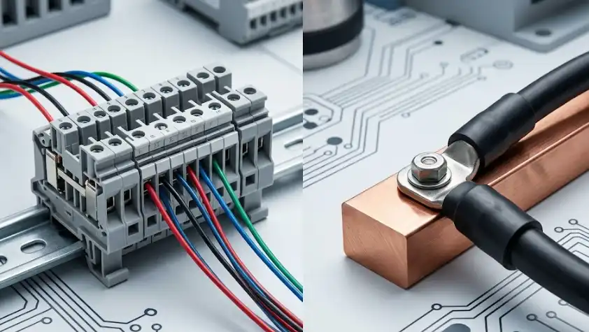
Over 60% of electrical panel wiring errors trace back to one decision: choosing the wrong connection method for the job. The terminal block vs bus bar difference comes down to purpose — terminal blocks create organized, individual point-to-point wire connections, while bus bars distribute a single electrical source to multiple circuits simultaneously through a shared conductive strip. Pick the wrong one, and you’re looking at voltage drops, overheating, or a maintenance nightmare that costs far more than the component itself.
This guide breaks down exactly how each device works, where each one belongs, and the scenarios where you actually need both in the same enclosure — so you can spec your next panel with confidence instead of guesswork.
Quick Answer — Terminal Block vs Bus Bar at a Glance
The core terminal block vs bus bar difference comes down to one word: routing. A terminal block connects individual wires point-to-point — think of it as an organized junction that joins Wire A to Wire B inside an enclosure. A bus bar, by contrast, takes a single electrical source and fans it out to multiple branch circuits simultaneously.
The simplest way to remember it: terminal blocks organize connections; bus bars distribute power.
Terminal blocks typically handle 20 A–150 A per connection point and use screw-clamp, spring-cage, or push-in mechanisms to secure conductors. Bus bars are solid copper or aluminum strips rated anywhere from 100 A to several thousand amps, bolted directly inside panels or switchgear. One replaces a tangle of individual splices; the other replaces a web of parallel feeder wires.
Why does this matter for your project? Choosing the wrong component can mean oversized panels, unnecessary cost, or — worse — a safety hazard from exceeding current ratings. The sections below break down every practical difference between terminal blocks and bus bars, including current capacity, wire gauge compatibility, cost, and real installation scenarios so you can pick the right one with confidence.
What Is a Terminal Block and How Does It Work
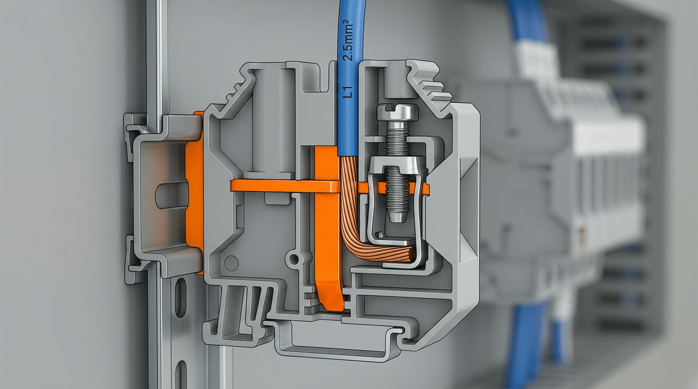
A terminal block is a modular connector that joins two or more wires inside an insulated housing. Each connection point is independent — one wire in, one wire out — which makes troubleshooting and rewiring straightforward without disturbing adjacent circuits.
The construction is simple but effective. A conductive metal strip (usually tin-plated copper or nickel-plated brass) sits inside a thermoplastic or ceramic body. A clamping mechanism — screw clamp, spring cage, or push-in design — secures the conductor against this strip. Most terminal blocks snap onto standard 35mm DIN rails per IEC 60947-7-1, though PCB-mount and barrier-style variants exist for other applications.
Common Terminal Block Types
- Feed-through: The workhorse — passes a circuit straight through from input to output.
- Fused: Integrates an inline fuse holder for overcurrent protection on individual circuits.
- Ground (earth): Bonds directly to the DIN rail or enclosure for grounding continuity.
- Disconnect: Features a knife-blade switch so you can isolate a circuit without pulling wires.
Why do electricians prefer them for organized termination? Because each wire lands on its own clearly labeled point. When you’re grasping the terminal block vs bus bar difference, think of terminal blocks as individual mailboxes — every circuit gets a dedicated slot. Brands like Phoenix Contact, Weidmüller, and Wago dominate this space, with spring-cage designs from Wago increasingly replacing traditional screw clamps for faster installation in control panels.
What Is a Bus Bar and How Does It Work
A bus bar is a solid strip of conductive metal — typically copper or aluminum — that serves as a common connection point for multiple circuits. Instead of routing individual wires between components, a bus bar distributes power from a single input across many output connections simultaneously. Think of it as a highway versus the individual streets that terminal blocks manage.
Construction is straightforward but heavy-duty. Most bus bars are flat, rectangular bars ranging from 1/4-inch to 1/2-inch thick, though tubular and round profiles exist for high-amperage applications. Copper bus bars dominate because of their superior conductivity (about 400 S/m), while aluminum versions cost roughly 60% less and weigh half as much — a tradeoff many engineers accept for large-scale installations.
Common Bus Bar Types
- Neutral bars — collect all neutral return conductors in a load center
- Ground bars — bond equipment grounding conductors to the panel enclosure
- Power distribution bus bars — carry 100 A to 6,000+ A in switchgear and industrial panels
Where does the terminal block vs bus bar difference become most obvious? Inside a panelboard or switchgear assembly. Bus bars run vertically or horizontally as the main power backbone, while branch circuits tap off them through breakers or fuses. Schneider Electric’s Prisma and ABB’s MNS systems both rely on bus bar architectures rated above 4,000 A for industrial distribution.
Bus bars excel at one job: moving large amounts of current across short distances with minimal voltage drop and heat buildup.
Key Differences Between Terminal Blocks and Bus Bars — Side-by-Side Comparison
Specs tell the real story. The table below captures every major terminal block vs bus bar difference across the criteria that actually matter when you’re specifying components for a panel or distribution system.
| Criterion | Terminal Block | Bus Bar |
|---|---|---|
| Primary Function | Point-to-point wire routing & organization | Common power distribution to multiple circuits |
| Construction Material | Brass or nickel-plated copper contacts in nylon/PA66 housing | Solid copper or aluminum strip, often tin-plated |
| Typical Current Capacity | 10 A – 150 A per pole | 100 A – 6,000 A+ |
| Mounting Method | DIN rail (35 mm) snap-on or PCB solder | Bolt-on standoff insulators or panel studs |
| Connection Type | Screw clamp, spring cage, or push-in | Bolted lug, set-screw, or stab-in |
| Modularity | High — add or remove individual poles freely | Low — fixed length, cut-to-size, or pre-drilled |
| Voltage Drop | Higher across multiple junctions | Minimal — single conductive path |
| Typical Applications | Control panels, signal wiring, field I/O | Switchgear, PDUs, battery banks, solar combiners |
One pattern jumps out: terminal blocks excel at organized, lower-current connections where you need easy maintenance access, while bus bars dominate wherever raw ampacity and minimal resistance are non-negotiable. Choosing between them isn’t about “better” — it’s about matching the component to the electrical job.
When to Use a Terminal Block vs a Bus Bar — Real-World Scenarios
Knowing the terminal block vs bus bar difference matters most when you’re standing in front of an open enclosure deciding what to mount. Here’s a scenario-by-scenario breakdown.
- Control panels & DIN-rail automation: Terminal blocks win. You need individual wire-to-wire connections for PLCs, relays, and sensors — each circuit isolated and labeled for fast troubleshooting.
- Residential breaker panels: Bus bars are standard. A single copper bar distributes 100–200 A from the main breaker to every branch circuit efficiently.
- Industrial machinery (50+ A feeds): Bus bars handle high-current trunk lines between drives and disconnects, while terminal blocks manage low-current signal wiring on the same backplane.
- Solar installations: Combiner boxes typically use bus bars to merge parallel string outputs before feeding an inverter — fewer connection points mean lower resistance losses.
- Automotive & marine wiring: Compact terminal blocks suit 12–48 V branch circuits where vibration-resistant, individually fused connections prevent cascading failures.
The reasoning is consistent: choose a bus bar when multiple circuits share one source at high current, and choose terminal blocks when each conductor needs its own discrete, serviceable connection point.
Using Terminal Blocks and Bus Bars Together in the Same Panel
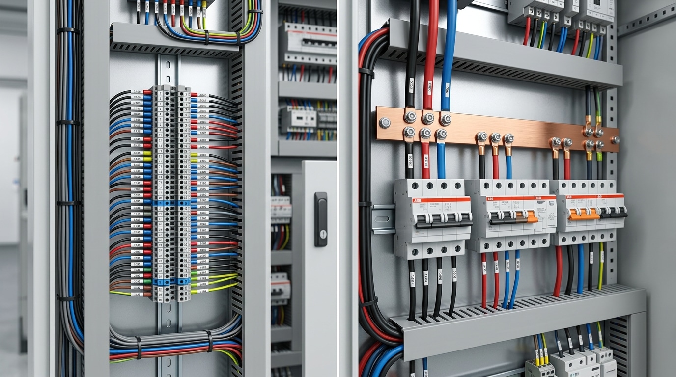
Here’s what experienced panel builders already know: the terminal block vs bus bar difference doesn’t force an either/or decision. In most industrial control cabinets, both components work as a team. A copper bus bar handles the heavy lifting — distributing 100A+ from the main breaker — while DIN-rail terminal blocks branch that power out to individual circuits, sensors, and relays.
Think of it as trunk-and-branch architecture. The bus bar is the trunk; terminal blocks are the branches.
Best Practices for Combining Them
- Layout: Mount bus bars at the top or side of the panel, with terminal block rows positioned below for short, clean wire runs.
- Labeling: Use ferrule markers on every wire landing on a terminal block and engrave or tag each bus bar section with its voltage and phase designation.
- Serviceability: Leave at least 25 mm of clearance between bus bar connections and the nearest terminal block row — technicians need finger access for torque checks.
- Color coding: Follow IEC 60445 standards: brown/black/grey for phases, blue for neutral, green-yellow for PE ground.
Weidmüller and Phoenix Contact both publish panel layout guides showing exactly this complementary approach. When you understand the terminal block vs bus bar difference as a spectrum rather than a rivalry, your panels get smaller, cooler, and far easier to troubleshoot.
Current Rating, Wire Size, and Safety Considerations
Oversizing is annoying. Undersizing kills. The most dangerous terminal block vs bus bar difference shows up when engineers ignore amperage limits or skip derating calculations for elevated ambient temperatures.
Standard terminal blocks typically handle 10 A to 150 A depending on wire gauge — a 10 AWG screw-clamp block might be rated 60 A at 25 °C. Copper bus bars, by contrast, routinely carry 200 A to 4,000 A+. But those ratings assume a 30 °C ambient. Push enclosure temps to 55 °C and you must derate by 20–30%, per IEC 60947-7-1 guidelines.
Common Mistakes That Violate Code
- Overloading bus bars by tapping too many branch circuits without recalculating total load — each tap adds resistance at the connection point.
- Mixing wire gauges in a single terminal block position, which reduces clamp pressure on the smaller conductor and creates hot spots.
- Ignoring torque specs — UL 486E specifies exact values (e.g., 35 in-lb for a #10 screw). Under-torqued connections arc; over-torqued ones crack housings.
Always verify UL 1059 (terminal blocks) or UL 67 (bus bar panelboards) listings before specifying components. For international projects, confirm IEC 60947-7 compliance. These certifications aren’t optional — they’re your legal shield during an inspection or incident investigation.
Cost Comparison and Practical Availability
A single DIN-rail terminal block costs $0.50–$3.00 per point, while a copper bus bar rated for 100 A might run $8–$25 per unit. Looks like bus bars lose on price, right? Not so fast. One bus bar replaces dozens of individual wire jumpers, so total installed cost — including labor, ferrules, end covers, and DIN rail — often favors the bus bar in high-distribution panels.
Labor is the hidden variable. Terminating 20 wires into screw-clamp blocks takes a technician 30–45 minutes. Bolting those same circuits onto a pre-drilled bus bar? Under 15 minutes. At shop rates of $75–$120/hour, that gap matters more than the component price tag.
When evaluating the terminal block vs bus bar difference on cost alone, always calculate per-circuit installed cost — not per-unit catalog price.
Availability is rarely an issue for standard ratings. Distributors like Digi-Key, Mouser, and AutomationDirect stock Wago, Phoenix Contact, and Weidmüller terminal blocks alongside copper and tin-plated bus bars for same-day shipping. Specialty items — high-voltage bus bars rated above 1,000 A or ATEX-certified terminal blocks — can carry 4–8 week lead times, so plan procurement early for those projects.
Bottom line: don’t let a cheaper unit price push you toward a solution that doubles your wiring labor or compromises safety. Factor in every accessory and every minute of installation time before deciding.
Frequently Asked Questions About Terminal Blocks and Bus Bars
Can a bus bar replace a terminal block? Only in specific scenarios. A bus bar distributes one source to many outputs — it doesn’t route individual circuits. If you need point-to-point wire management with separate connections, a terminal block is irreplaceable. Swapping one for the other ignores the fundamental terminal block vs bus bar difference in function.
Are bus bars safer than terminal blocks? Not inherently. Safety depends on correct sizing, torque specs, and enclosure. An exposed bus bar is arguably riskier because it carries high current on an uninsulated conductor. Terminal blocks with touch-safe housings rated to IEC 61010 offer better finger protection in low-voltage panels.
What’s the maximum amperage for each? Standard DIN-rail terminal blocks top out around 150–200 A. Copper bus bars? They scale past 5,000 A in switchgear applications. The gap is enormous.
Do terminal blocks add resistance? Yes — every connection point introduces contact resistance, typically 0.1–0.5 mΩ per junction. For signal-level or moderate-current circuits, this is negligible. At 200 A+, that micro-resistance generates real heat, which is exactly why bus bars win at high current.
Can I use one bus bar for both grounding and neutral? Not in the same panel downstream of the main disconnect. NEC Article 250.24 requires separate neutral and ground bus bars in sub-panels to prevent objectionable current on equipment grounding conductors. Combining them is only permitted at the service entrance.
Making the Right Choice for Your Project
Before you order anything, ask yourself three questions:
- How many amps? Under 30 A with multiple discrete circuits — terminal blocks win. Over 100 A on a shared distribution path — bus bar, no contest.
- Do I need individual wire identification and easy disconnection? If yes, terminal blocks give you labeled, per-circuit isolation that a bus bar simply can’t match.
- Am I distributing one source to many branches? That’s exactly what a bus bar is engineered for — fewer connections, lower voltage drop, and a smaller footprint than daisy-chaining terminals.
Most well-designed panels use both. A copper bus bar feeds main power; terminal blocks break it out to field devices. Understanding the terminal block vs bus bar difference isn’t about picking a winner — it’s about placing each component where it performs best.
Rule of thumb: route with terminal blocks, distribute with bus bars. When the two overlap, combine them and let each do its job.
Get the selection right and you gain safer terminations, faster troubleshooting, and a panel that passes inspection the first time. Get it wrong, and you’ll be re-wiring under deadline pressure — which nobody enjoys.
See also
Inside a Breaker Box Everything You Need to Know
How to Wire a Circuit Breaker Panel Safely at Home
Single Phase Distribution Box Definition and Main Parts
Wholesale MCB vs. Individual Circuit Breakers
Understanding Distributed Generation in Electrical Engineering

Discover more from SENTOP Electrical Co., Ltd
Subscribe to get the latest posts sent to your email.
