
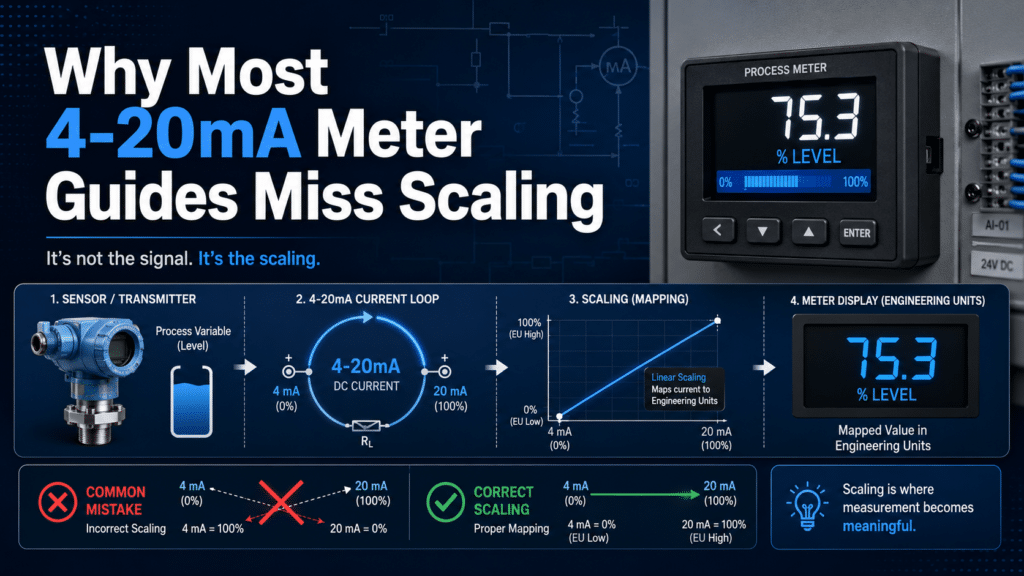
A 4-20mA digital panel meter converts a current loop signal into readable engineering units by mapping 4 mA to approximately 0%[1] of range and 20 mA to approximately 100%, then scaling those endpoints to real values like pressure or temperature. For example, a sensor reading 0–100 PSI shows 0 at 4 mA and 100 at 20 mA, with 12 mA displaying 50 PSI. This 4-20mA Digital Panel Meter Guide explains the scaling step most tutorials skip, since current loops resist noise over runs exceeding 1,000 feet.
By the end, you’ll understand a few things. How does a 4-20mA digital panel meter actually work? Why does the scaling go wrong so often? Which settings really matter when you’re choosing a meter? How do you wire and configure one, step by step? And what kinds of mistakes lead to that frustrating “out of range” error everyone dreads?
Quick Takeaways
- Map 4 mA to sensor low and 20 mA to high before wiring.
- Use current loops to resist noise over runs exceeding 1,000 feet.
- Leverage live zero at 4 mA to detect broken wires instantly.
- Fix display errors by correcting scaling, not rewiring terminals.
- Set decimal point and engineering units before shipping meters to operators.
Why do most 4-20mA meter guides get scaling wrong?
Most 4-20mA meter guides get the scaling part wrong because they treat the meter like something you just plug in, and they skip over the math that maps the loop current to actual engineering units. They show you how to wire up two terminals, and then they stop right there. They never bother explaining that 4 mA has to equal your sensor’s low reading and 20 mA has to equal its high reading. Without doing that step, your display ends up showing a number that essentially means nothing at all.
This 4-20mA Digital Panel Meter Guide takes an engineer’s workflow instead. You scale the loop first, then wire it, then calibrate it, and then you verify it against a known input. Product pages will list cutout sizes and digit counts. They rarely show you the formula that turns 12 mA into 50 PSI.
What does “plug-and-play” miss in real installs?
Plug-and-play guides miss the fact that a 4-20mA loop carries no units at all. It carries current, and the meter has no idea what that current is actually supposed to represent. The 4,20 mA standard gets used so widely because current resists signal loss and electrical noise over long cable runs better than voltage does. But the meter still needs you to define the range yourself.
Think of it like a thermometer with no numbers printed on it. The mercury still moves up and down. You just can’t read what it says. A 4-20mA meter without scaling is that same blank scale.
Here is where the guides tend to fail when you actually use them:
- No transmitter range stated: A pressure transmitter rated 0–100 PSI sends 4 mA at 0 and 20 mA at 100. Skip this and your “50 PSI” reading might really be 30.
- Offset confused with span: Offset sets the low value, which is the 4 mA point. Span sets the high value, the 20 mA point. Adjusting one shifts the whole scale around.
- Decimal point ignored: Display shows 1000 instead of 100.0 because a switch was never set in the first place.
What does this guide cover that product pages skip?
This guide covers the full initial startup workflow, the scaling math, loop power budgeting, wiring polarity, two-point calibration, and field troubleshooting, all in the order that a working technician actually performs them. Product pages just give you specs. They don’t give you the sequence.
One number proves the point really well. A 4,20 mA loop needs a DC supply rated at least 10% above the sum of every device voltage drop, according to Schneider Electric’s 2020 application guidance. Forget about that headroom and the loop drops below 4 mA under load, so your meter reads a fault even when nothing is actually broken.
We also cover the edge cases most guides skip over completely: stuck readings, 0 mA loss-of-signal faults, and slow drift over the span of months. These are the problems that send techs back to the panel at 2 a.m., and they’re the reason scaling done right the first time really saves you actual money.

What does a 4-20mA digital panel meter actually do?
A 4-20mA digital panel meter is a signal converter. It reads the current flowing through a 4-20mA loop and displays that current as a number in real engineering units, like 0 to 150 PSI or 32 to 212°F. The meter doesn’t measure pressure or temperature directly. It measures milliamps and translates them. Engineers use the 4-20mA standard because current resists signal loss and electrical noise over long cable runs better than voltage, per Schneider Electric’s 2020 guidance.
Picture a sensor at one end of a long wire and your meter at the other. The sensor pushes a precise current into the loop based on what it senses. Your panel meter sits in that loop and reads the current passing through it.
Why is 4mA the live zero instead of 0mA?
4mA is the live zero because it proves the loop is alive even when the measured value is zero. If the sensor reads zero pressure, it still sends 4mA, not nothing. This is the genius of the standard. A real 0mA reading means something broke: a cut wire, a dead transmitter, or a loose terminal.
This trick is called Live-zero fault detection. With a 0-20mA system, a snapped wire and a true zero reading look identical. You’d have no way to tell. With 4-20mA, any reading below 4mA, say 2mA or 0mA, instantly flags a fault. Good meters detect this and show a “0mA” or open-loop alarm instead of a fake low number.
- 4mA: The bottom of your scale (e.g., 0 PSI), confirming a healthy loop.
- 20mA: The top of your scale (e.g., 150 PSI), full signal.
- Below 4mA: A fault — broken wire, failed sensor, or wiring error.
Where does the meter sit in the loop?
The meter sits in series with the loop, acting as a receiver. Current flows from the power supply, through the transmitter, then through the panel meter, and back. Some meters, like the Precision Digital PD765, can run as loop-powered displays that draw their operating power from the same 4-20mA current, no separate supply needed.
That said, your loop’s DC supply must have headroom. Schneider Electric’s 2020 application notes specify a supply voltage at least 10%[2] higher than the sum of every device’s voltage drop in the loop. Skip this math and your meter may display a frozen or dim reading. This 4-20mA Digital Panel Meter Guide returns to that calculation in the wiring section, because undervolted loops are a top field failure.

How do you scale 4-20mA to real engineering units like PSI, GPM, or °C?
You scale a 4-20mA signal using the linear equation Y = mx + b, where x is the milliamp reading, m is the span ratio, and b is the offset. What this means in practice is that the 4mA point represents the lowest value your sensor can report, and the 20mA point represents the highest value it can report. The Omron K3MA series, for example, lets you map 4mA to a display of 0 and 20mA to 100 kPa, according to its 2021 user manual. Once you get those two anchor points correct, every reading that sits between them falls into place automatically.
How do you scale a 0-100 PSI pressure sensor?
You map 4mA to 0 PSI and 20mA to 100 PSI. The current span, meaning the range of the signal itself, works out to 20 − 4 = 16mA. The engineering span, which is the range of the actual pressure you care about, is 100 − 0 = 100 PSI. So the slope m comes out to 100 ÷ 16 = 6.25 PSI for every milliamp of signal.
The full equation becomes Y = 6.25 × (x − 4). Subtracting 4 takes care of the offset, considering that your zero point actually sits at 4mA rather than at 0mA. You can test it pretty easily. At 12mA, which is the middle of the scale, y = 6.25 × 8 = 50 PSI, which is correct.
At 20mA, y = 6.25 × 16 = 100 PSI. A meter that displays 0-100 needs no decimal point, so you simply set the display to whole numbers.
How do you scale a 4-200°C temperature sensor?
This one tends to trip people up because the low value is not zero. You map 4mA to 4°C and 20mA to 200°C. The engineering span here is 200 − 4 = 196°C. The slope m works out to 196 ÷ 16 = 12.25°C for every milliamp.
The equation becomes Y = 12.25 × (x − 4) + 4. That “+ 4” is your offset b, which is the value shown on the display at the very bottom of the loop. You can check it at 4mA, where y = 0 + 4 = 4°C[3]. At 20mA, y = 12.25 × 16 + 4 = 200°C.
Both anchor points land exactly where they should. Since the highest reading is 200, a 3½-digit display shows it cleanly without any digits getting cut off.
| Parameter | 0-100 PSI sensor | 4-200°C sensor |
|---|---|---|
| Display at 4mA (offset b) | 0 | 4 |
| Display at 20mA | 100 | 200 |
| Engineering span | 100 PSI | 196°C |
| Slope m (per mA) | 6.25 | 12.25 |
| Decimal point | None (0-100) | None (4-200) |
Where does the decimal point fit in?
The decimal point is a display setting, and it is not part of the math itself. If your sensor reads 0-10.0 PSI, you scale to 0-100 first, then shift the decimal one place to the left so the meter shows 10.0. On many units, a single switch controls this. The Farnell DP8180-class meter uses SW1 to set both the decimal point and the offset, according to its 2024 datasheet.
You really need to set the scaling and the decimal placement together, otherwise your reading will be off by a factor of ten. This pairing is the step that most weak 4-20mA Digital Panel Meter Guide write-ups skip entirely.

Loop-powered vs externally-powered meter — which should you wire?
You should only wire a loop-powered meter when your 24VDC supply still has enough room left over after the transmitter and the wiring take their share. A 4,20 mA loop needs a supply voltage that sits at least 10% above the total of every device drop, according to Schneider Electric’s 2020 application guidance. Meters that draw their power from an outside source skip this budget entirely, since they pull their display power from a separate feed. So the question that really matters is a simple one: does your loop actually have spare volts to give?
How do you calculate the loop voltage budget?
You add up every voltage drop that happens in series, and then you compare that total against your supply. The loop is essentially one single circuit. That same 4,20 mA current flows through the transmitter, through the meter’s burden resistor, and through the wire itself. Each of those pieces takes a little voltage along the way.
- Transmitter minimum operating voltage: this is often 12V measured at the transmitter terminals (check the datasheet, since many pressure transmitters need somewhere between 10.5 and 12V[4] just to function).
- Meter burden voltage: this is the drop across the meter’s input resistor. A loop-powered display can ask for 3 to 4V, while a passive sense resistor may drop under 1V.
- Wiring drop: this is the current multiplied by the total loop resistance. Copper 18 AWG runs about 6.4 ohms per 1000 ft, so a 500 ft round-trip at 20 mA drops roughly 0.13V[5].
When does a 24VDC loop run out of headroom?
It runs out when the stacked drops plus that 10% margin go beyond 24V. Walk through a real loop and you’ll see it clearly: a transmitter that needs 12V, a loop-powered meter dropping 4V, and another 0.2V lost in the wiring.
That all sums to 16.2V[6]. Multiply that by 1.1 to cover the safety margin and you end up needing 17.8V, which sits comfortably on a 24V supply.
But now add a 250-ohm HART resistor, which is a 5V drop, and then put a second display in series, which is another 4V. The stack jumps all the way to 25.2V before you even apply the margin. Your 24V[7] supply simply can’t push that much. The loop-powered meter starves for power, the transmitter clamps down, and the reading either drifts low or freezes up completely.
| Topology | Power source | Voltage cost to loop | Best use case |
|---|---|---|---|
| Loop-powered | The 4–20 mA loop itself | 3–4V burden added to budget | Short runs, single display, simple sensors |
| Externally-powered | Separate 24VDC or 120VAC feed | Under 1V (passive sense) | Long runs, HART, multiple devices in series |
Here is the trap that most installers miss: loop-powered meters look cheaper and cleaner on paper, but they end up eating your scarcest resource, which is voltage. This 4-20mA Digital Panel Meter Guide generally suggests mapping out the budget before you place your order. If the stack ends up above 70% of your supply, switch over to an externally-powered meter and reserve the loop for carrying current only. And verify your transmitter’s exact minimum terminal voltage against the manufacturer datasheet, not against some generic figure.

How do you wire the 4-20mA input correctly?
Wire the 4-20mA input by putting the meter in series with the loop, never in parallel. Current must flow through the meter’s sense resistor and back to the supply. The standard works because current stays constant along the whole loop, so it resists signal loss and noise over long cable runs, per Schneider Electric’s 2020 loop guidance. Get the series path right and your reading tracks the transmitter exactly.
The trickiest part of any 4-20mA Digital Panel Meter Guide is the transmitter type. Two-wire, three-wire, and four-wire transmitters all carry the same 4-20mA signal, but they handle power differently. Match the wiring to the device on the nameplate.
How do you wire 2-wire, 3-wire, and 4-wire transmitters?
Run the loop current in series through the meter for all three types; only the power return path changes. A 2-wire device shares power and signal on the same pair. A 3-wire adds a separate common. A 4-wire keeps power fully isolated from signal.
| Transmitter type | Wires | Meter placement | Power source |
|---|---|---|---|
| 2-wire | 2 | Series in the + supply leg or return leg | Loop current (24VDC) |
| 3-wire | 3 | Series in signal leg, shared common | Separate V+ and GND |
| 4-wire | 4 | Series in isolated signal loop | Own power pair, isolated output |
Where does the sense resistor go and how do you ground the shield?
Place the sense resistor inside the meter’s input terminals, in series with the loop, most panel meters have it built in at a fixed value like 100Ω or 250Ω. A 250Ω resistor turns 4-20mA into a clean 1-5V drop the meter’s ADC reads. Never add a second external resistor unless the meter input is true voltage; doubling resistance breaks your scaling math.
Ground the cable shield at one end only, usually the power supply or panel ground bus. Grounding both ends creates a ground loop, a small circulating current that injects noise and can shift your reading by several counts. Single-point grounding kills that loop. Confirm the supply has at least 10%[8] voltage headroom over total loop drops, including transmitter, wiring, and the meter’s burden.
What’s the most common reversed-polarity mistake?
Swapping the + and − loop terminals is the number-one field error. On a 2-wire transmitter, reversed polarity blocks current entirely, so the meter reads 0mA or a dead display, easy to mistake for a failed transmitter. Some meters survive reverse connection thanks to a protection diode; many older units don’t and can be damaged.
Wiring diagram callout: 24VDC (+) → transmitter (+) → transmitter (−) → meter terminal (+) → meter terminal (−) → 24VDC (−). The current makes one clean loop. Trace it with your finger before powering up.
Before energizing, verify continuity with the supply off, then clamp a meter in series to confirm the loop draws between 4 and 20mA. A reading stuck at exactly 0mA almost always means reversed leads or an open terminal, not a sensor fault.
How do you calibrate and verify the displayed reading?
Calibrate a 4-20mA digital panel meter by injecting a precise 4mA signal and setting the zero (low-scale) value, then injecting 20mA and setting full-scale. Typical calibration requires applying an accurate 4mA signal, adjusting the offset until the display reads the low value, then applying 20mA and adjusting span, per 2024 panel meter datasheets. Repeat until both points hold steady.
You need a current source the meter can trust. A handheld loop calibrator or a precision current source injects exact milliamp values into the input terminals. Skip the cheap bench supply, it drifts. A good loop calibrator holds output to within 0.01mA, far tighter than the meter’s own display resolution.
How do you set zero and full-scale with a calibrator?
Inject 4.000mA, enter the meter’s input menu, and store that point as your low reading (often “INP LO” or “4mA CAL”). Then inject 20.000mA and store it as the high reading. On PD765-style menus, you scroll to the calibration screen, hold Enter to capture the live current, then type the engineering value you want displayed, say 0 PSI at 4mA, 300 PSI at 20mA.
Verify linearity at midscale. Inject 12.000mA. A correctly scaled meter showing 0,300 PSI must read 150 PSI, dead center. If it reads 148 or 153, your span point is off, re-store 20mA. Any meter using true two-point linear math will track midscale automatically once both endpoints are correct.
Can you calibrate in the field without a calibrator?
Yes, use a known sensor value as your reference. Park the process at a stable, measurable condition (a tank at a verified level, a line at ambient temperature), read the actual value with a trusted instrument, then nudge the meter’s offset until the display matches. This is single-point trim, not full calibration, but it corrects drift between scheduled checks.
The catch: field trim only fixes offset, not span. If your sensor reads correct at low flow but high at full flow, you’ve a span error that no single-point field tweak can fix. Plan a full two-point recalibration with a calibrator at the next maintenance window.
| Method | Tool needed | Corrects | Typical accuracy |
|---|---|---|---|
| Two-point calibration | Loop calibrator (±0.01mA) | Offset + span | ±0.1% of span |
| Single-point field trim | Known sensor value | Offset only | ±1% or worse |
| Midscale verification | 12mA injection | Confirms linearity | Pass/fail check |
Document every calibration with the date, injected currents, and as-found versus as-left readings. This 4-20mA Digital Panel Meter Guide treats that log as non-negotiable, auditors in regulated plants demand it, and a drift trend across logs warns you of a failing sensor before it causes a process upset.
How do you troubleshoot a stuck reading, 0mA fault, or signal drift?
Troubleshoot a 4-20mA fault by isolating where current stops flowing: the transmitter, the wiring, or the meter. A reading below 4mA almost always means a broken loop, since the 4-20mA standard uses current that resists noise over long cable runs, per Schneider Electric’s 2020 loop guidance. So your first move is a clamp meter on the loop, not a panel reset.
Grab a multimeter set to DC milliamps. Break the loop and read it in series. If you see 0mA, the circuit is open somewhere. If you see steady 12mA but the display is frozen, the problem lives inside the meter or its scaling.
What does each symptom point to?
Different faults leave different fingerprints. A frozen number behaves nothing like a slow drift. Match the symptom to the test point below before you start swapping parts.
| Symptom | Test point | Likely cause | Fix |
|---|---|---|---|
| Display reads below 4mA (0–3.5mA) | mA in series at meter terminals | Open loop, blown transmitter, dead 24VDC supply | Trace continuity, confirm supply has 10% headroom |
| Frozen number, never changes | Inject known 12mA signal | Failed input stage or stuck scaling lock | Replace meter or clear configuration lock |
| Slow drift over hours | Compare meter vs source calibrator | Failing transmitter, temperature on sensor | Recalibrate transmitter, check ambient temp |
| Erratic jumps or flicker | Scope the loop, check shield ground | EMI, ground loop, loose terminal | Single-point ground shield, torque terminals |
How do you tell EMI from a ground loop?
EMI and ground loops both cause erratic readings, but the cure differs. A ground loop happens when the cable shield is grounded at both ends, creating a circulating current that rides on your signal. Ground the shield at one end only, usually the control panel.
EMI (electromagnetic interference from motors or VFDs) shows up as random spikes, often timed to a nearby pump cycling. Reroute the loop cable away from power lines. Keep at least 30cm of separation. A variable frequency drive 1 meter away can inject enough noise to swing a reading by several percent.
Why does a sub-4mA reading mean broken loop, not low process?
A healthy 4-20mA loop never drops below 4mA in normal operation, that 4mA floor is the “live zero” that proves the wire is intact. Reading 2mA or 0mA means current has stopped, not that your tank hit zero. This live-zero diagnostic is the core advantage covered throughout this 4-20mA Digital Panel Meter Guide: a true zero process value still draws 4mA, so any value below it flags a hardware failure.
Check these in order:
- 24VDC supply: measure terminal voltage live — a sagging supply starves the loop
- Transmitter output: inject a calibrator in place of the transmitter; if the meter reads correctly, the transmitter failed
- Terminal torque: a loose screw at 0.5 N·m adds resistance that drops voltage below the loop’s minimum
Document each test point reading. A logged 11.8mA at the panel but 4mA at the source instantly locates a bad cable splice.
What scaling and wiring mistakes cause the most field errors?
The four mistakes that wreck the most initial startup jobs are scaling to the wrong range, missing decimal points, dual grounding, and burden-voltage starvation. The first two corrupt your reading; the last two make a healthy loop look broken. Catch them before you blame the sensor, they account for the bulk of “the meter is wrong” service calls.
Why does scaling to the sensor range instead of transmitter output cause silent errors?
Scaling to the sensor’s physical range instead of the transmitter’s configured 4-20mA span gives readings that look plausible but are flat wrong. Say a pressure transmitter physically tops out at 250 PSI, but its 4-20mA span is set to 0-100 PSI. If you scale your meter to 250 PSI at 20mA, every reading reads 2.5x too high. Nothing trips an alarm. The display just lies.
Always pull the transmitter’s Configured span from its datasheet or HART read-back, not the sensor’s catalog max. These two numbers disagree more often than you’d think, because integrators turn down spans to improve resolution.
How do decimal-point and ground-loop errors show up?
A misplaced decimal point turns 75.0 °C into 750 °C[9] or 7.50. On meters with a jumper or switch for decimal position (common on multi-input boards where SW1 sets decimal point and offset), forgetting this step is the single most common scaling slip. Set the decimal first, then calibrate span.
Ground loops come from grounding the loop at two points, once at the transmitter and again at the power supply or meter chassis. The two ground potentials differ by a few millivolts, and that difference pushes stray current through the signal path, adding noise or a steady offset. The 4-20mA standard resists noise precisely because current survives long cable runs better than voltage, but dual grounding throws that advantage away. Ground the loop at exactly one point, usually the power supply negative.
What’s burden-voltage starvation and why does it mimic sensor failure?
Burden-voltage starvation happens when the loop supply can’t push enough voltage to drive all the devices in series, so current can’t reach 20mA. The display caps out below full scale, looking exactly like a failing sensor. Industry guidance specifies the supply must sit at least 10% above the sum of every device’s voltage drop. Add up the transmitter’s minimum (often 12V), wire resistance, and each receiver’s burden before you trust a 24VDC supply.
| Mistake | Symptom | Fix |
|---|---|---|
| Wrong span source | Reading off by a fixed ratio | Use transmitter’s configured span |
| Decimal misplaced | 10x or 100x display error | Set decimal before calibration |
| Dual grounding | Noise or steady offset | Ground at one point only |
| Burden starvation | Reading caps below 20mA | Supply ≥ sum of drops + 10% |
Work through these four before reading the FAQs in this 4-20mA Digital Panel Meter Guide, most field tickets close right here.
Frequently asked questions about 4-20mA digital panel meters
The four questions field techs ask most about a 4-20mA digital panel meter are: where to find the PD765 manual, why the display reads zero, whether you need a sense resistor, and how the 6R0 and 6R3 model variants differ. Short answers below, each one fixes a problem that stalls real initial startup jobs.
Where do you find the PD765 manual and wiring diagram?
Download the PD765 manual directly from the manufacturer’s product page, not a third-party PDF mirror. Reseller copies often lag a firmware revision behind, so the menu maps no longer match the unit in your hand. The genuine document includes the DIP switch table, terminal pinout, and the loop-power voltage budget you need before wiring.
One practical tip: match the manual’s revision letter (printed on the cover) to the label on your meter. A mismatch means a different decimal-point or calibration menu structure.
Why does my 4-20mA panel meter read zero?
A zero reading almost always means no current is reaching the meter, not that the meter is broken. The most common cause is an open loop: a loose terminal, reversed polarity, or a transmitter that lost its 24VDC supply. Remember, a healthy loop never drops below 4mA, so a true 0mA reading signals a fault, not a low process value.
Check three things in order. First, measure loop current with a meter in series, you should see 4 to 20mA. Second, confirm polarity at the input terminals. Third, verify your supply has enough headroom; the 2020 Schneider Electric application guidance recommends a DC supply at least 10% above the total of all device voltage drops. Starve the loop, and the display drops to zero.
Do you need a sense resistor with a 4-20mA meter?
It depends on the input type. A true current-input panel meter has its own internal shunt and needs no external sense resistor. A voltage-input meter, however, requires a precision resistor, typically 250Ω, to convert the 4-20mA loop into a 1-5V signal it can read.
Use a 0.1%[10] tolerance resistor, not a generic 5% part. A 250Ω resistor off by 5% shifts your full-scale reading by the same margin, which a calibration pass can’t fully correct.
What’s the difference between PD765 6R0 and 6R3 variants?
The suffix codes designate different option packages, usually power-input and relay-output configurations, not different display accuracy. The 6R0 and 6R3 share the same core display and 4-20mA front end; the difference lies in supplied power options and the number of installed alarm relays. Always cross-check the suffix against the ordering table in this 4-20mA Digital Panel Meter Guide’s referenced manual before swapping a spare, because a relay-equipped variant won’t slot into a basic socket.
Putting the commissioning workflow together
The full 4-20mA initial startup workflow is four ordered steps: Wire, scale, calibrate, verify. Skipping any one creates a meter that reads numbers but lies about the process. The step nearly every guide drops is scaling, the math that turns 4-20mA into PSI, GPM, or °C. Get the wire-scale-calibrate-verify sequence right and a single technician can commission a loop in under 20 minutes.
Why does order matter? Because each step assumes the previous one is locked. Calibrating before scaling means you tune the meter to a span it will never display. Verifying before calibrating means you confirm a wrong reading. Run them out of sequence and you chase ghosts.
What does the repeatable checklist look like?
Run these five checks in order on every install. Each one gates the next.
- Confirm burden voltage headroom: Add every voltage drop in the loop, then require a supply at least 10% above that sum, per Schneider Electric’s 2020 loop guidance. A 24VDC supply driving a transmitter, 250-ohm meter, and wiring rarely fails this — but a long run with three series devices can.
- Wire in series, polarity correct: The meter joins the loop in series so all 4-20mA flows through it. Reversed polarity reads 0mA.
- Scale the range: Apply y = mx + b. Set 4mA to your zero value and 20mA to your full-scale value. A 0-150 PSI transmitter maps 4mA→0 and 20mA→150.
- Calibrate the endpoints: Inject precise 4mA, set zero; inject 20mA, set span; repeat until stable.
- Verify at midpoint: Inject 12mA. The display must read exactly mid-scale (75 PSI for a 0-150 range). Off by more than 1% means your scaling math, not your calibration, is wrong.
Why is the midpoint verification step non-negotiable?
The 12mA midpoint check catches scaling errors that endpoint calibration hides. Calibrate zero and span perfectly, and a meter scaled to the wrong range still nails 4mA and 20mA, but the middle drifts. A 12mA injection on a correctly scaled 0-150 PSI loop must show 75 PSI. If it shows 80, your linear coefficients are off, and no amount of recalibrating the endpoints fixes it.
This is the test that separates a working install from a silent failure. Endpoints can be right while the slope is wrong. The midpoint is the only place that error shows.
How do you apply this on your next install?
Bring two numbers to the field before you touch a terminal: your total loop burden voltage and your scaling endpoints. Calculate the burden sum first, transmitter drop plus receiver impedance plus cable resistance, and confirm your supply clears it by 10%. Then write your 4mA and 20mA target values on the transmitter housing in marker. That habit alone prevents the most common scaling mistake: mapping to the meter’s default range instead of the transmitter’s actual range.
This 4-20mA Digital Panel Meter Guide gave you the math most pages skip. Run the burden-voltage calculation and the y = mx + b scaling on your next loop, verify at the 12mA midpoint, and you’ll commission meters that hold accuracy across the full span, not just at the two points everyone else checks.
Digital Meter Selection Support
Choose the Right SENTOP Digital Panel Meter for Your Application
After comparing different digital panel meter types, match your project with SENTOP models for voltage, current, frequency, power, and multi-function monitoring in control cabinets and distribution panels.
- ✓Ammeter, voltmeter and multi-function meter options
- ✓AC/DC and single/three-phase measurement
- ✓LED and LCD display configurations
- ✓Wholesale supply for panel builders and distributors
Find a suitable model for your panel design
Reference Sources
- [1]blog.se.com — supports: The 4–20 mA current loop standard is widely used in industrial process control to transm…
- [2]murata.com — supports: Digital panel meters such as the DMS-20PC-4/20 series are loop-powered 4–20 mA displays …
- [3]automationdirect.com — supports: AutomationDirect’s ProSense LPM1 loop panel meters are 1/8 DIN digital panel meters that…
- [4]omron.com — supports: The Omron K3MA series digital panel meters support 4–20 mA input scaling so that a 4 mA …
- [5]dwyer-inst.com — supports: Dwyer’s Series DPMW digital panel meter accepts a 4–20 mA input and uses a 24 VDC power …
- [6]farnell.com — supports: Farnell’s DP8180-class digital panel meters support multiple analog inputs including 4–2…
- [7]predig.com — supports: Modern digital panel meters like AutomationDirect’s DPM3 series offer optional 4–20 mA a…
- [8]instrumentation2000.com — supports: Manufacturers such as Instrumentation2000 and Sifam Tinsley market dedicated 4–20 mA DC …
- [9]sifamtinsley.com — supports: Manufacturers such as Instrumentation2000 and Sifam Tinsley market dedicated 4–20 mA DC …
- [10]scribd.com/document/994219282/D0002575-4-20mA-PANEL-DISPLAY-INSTALLATION-MANUAL — supports: Sonar real-time citation (HEAD-verified)

Discover more from SENTOP Electrical Co., Ltd
Subscribe to get the latest posts sent to your email.
