

What Is the Best Location for an Automatic Transfer Switch?
The best ATS location is the point in the power path that correctly connects the normal source, alternate source and intended loads while preserving the exact enclosure rating, access, wiring routes and utility/AHJ approval. In many projects that is near service equipment or an essential-load panel—but there is no universal wall, distance or indoor/outdoor answer.
A good ATS location passes every hard gate
Start with the backup objective. Will the system transfer an entire service, one feeder or a defined essential-load panel? Draw the normal source, alternate source, load, service disconnects and every battery, photovoltaic, UPS or generator path. The ATS belongs where that approved architecture places it.
A whole-service design often points toward the meter or main service area. A selective-load design often points toward the essential-load distribution point. A battery system may place a gateway or meter-mounted backup switch at a manufacturer-approved tie-in instead of using a conventional generator ATS. These are common patterns—not installation instructions.
The best location is not simply closest to the generator, driest today or easiest for conduit. It must match the exact assembly, remain accessible, protect the listed enclosure condition and survive authority review.
Four relationships determine the physical shortlist
A wall can look ideal yet place the ATS on the wrong side of the service disconnect, outside the intended backup boundary or in a route that cannot be approved.
Utility or preferred source to ATS
This path establishes the service/disconnect relationship, upstream protection, fault duty and utility responsibility.
Evidence: one-line, service data, available-fault-current study and utility/AHJ decision.Generator or approved backup to ATS
This path includes power plus start, ready, sensing, communications and source-specific grounding requirements.
Evidence: exact source manual, control interface and accepted conductor route.ATS to the defined load boundary
The connection decides what is actually backed up and whether optional demand needs automatic shedding or staged pickup.
Evidence: load schedule, backup scope, panel/feeder identity and capacity review.Bonding follows system design
Solid-neutral and switched-neutral systems can require different bonding, grounding-electrode and ground-fault arrangements.
Never add or remove a neutral-to-ground bond because the ATS or generator moved.Match the location to the backup boundary
Use this matrix to ask better questions. The approved one-line, equipment submittal and authority review still control the final location.
| System pattern | Leading location candidate | Why it can work | What can disqualify it |
|---|---|---|---|
| Whole-service standby generator | COMMON PATTERN At or near service/meter or main distribution equipment, under an approved service-transfer architecture. | It can place the intended building load on one clear transferred path without moving every branch circuit. | Non-service-rated equipment, utility restrictions, wrong fault rating, poor access, incorrect neutral/bonding design or unsuitable enclosure. |
| Essential-load backup | COMMON PATTERN Near the essential-load panel or the feeder that defines the selective backup boundary. | It keeps nonessential demand outside backup and makes the transferred load set easier to document. | A crowded panel area, inaccessible terminals, unclear load labels, an unsuitable route or a backup source that cannot carry automatic load pickup. |
| Downstream non-service ATS | TOPOLOGY GATE At an approved feeder/load point downstream of existing service equipment. | Service equipment can remain while a defined distribution section transfers. | Treating the ATS as a service disconnect, overlooking upstream OCPD conditions or placing it outside the intended load path. |
| Commercial or industrial lineup | ENGINEERED LAYOUT At the switchgear, distribution or generator lineup shown on engineered drawings. | Power routing, floor support, connection access, bypass/isolation and maintainability can be coordinated as an assembly. | Ignoring front/rear connections, cable bending, short-circuit ratings, adjacent sections or fire/life-safety project rules. |
| Solar or battery backup | APPROVED ARCHITECTURE At the documented meter, backup gateway, backup panel or service tie-in for that system. | Grid isolation, metering, source priority and backed-up loads can be coordinated in one manufacturer-approved design. | Adding a generic generator ATS without checking grid-forming, anti-islanding, meter, firmware, neutral and utility conditions. |
A product rating is not a location approval. Confirm the exact catalog number, service role, voltage/phase/current, short-circuit conditions, poles and neutral method, enclosure, entries, controls and complete-system certification before approving a wall or pad.
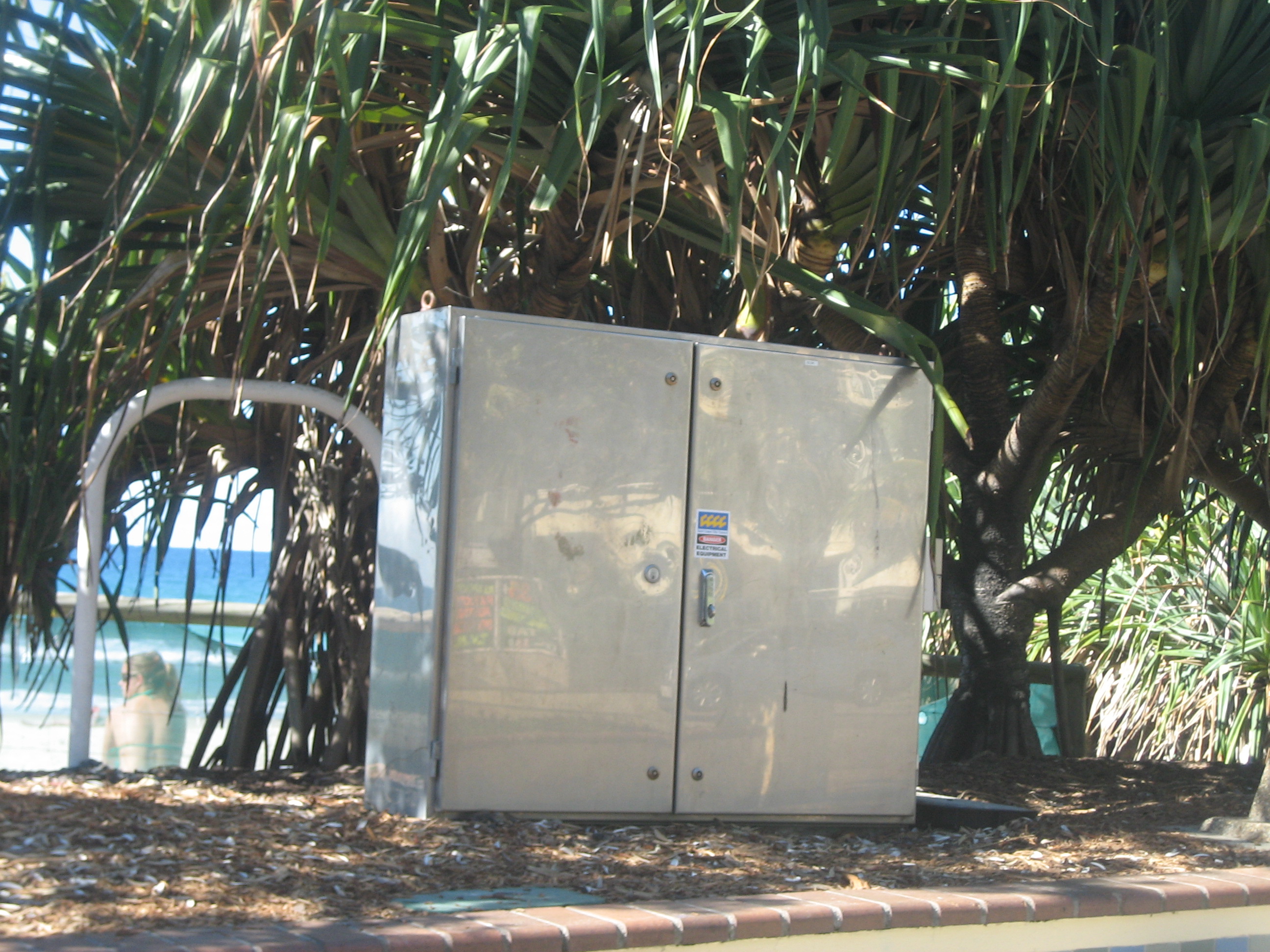
Match the complete enclosure system to the real environment
A Type 3R enclosure can be suitable indoors or outdoors when correctly installed, but it is not blanket permission for every site. The rating does not by itself cover internal condensation, corrosion, contamination, thermal damage, flood exposure or unsealed entries.
Check the enclosure, hubs, fittings, cable entries, mounting method and finished assembly together. Then compare them with rain, ice, sunlight, salt, chemicals, dust, lint, humidity, temperature, flood level and physical impact.
- Outdoor service area: verify weather exposure, corrosion, ice, access, utility work zone, entries and physical protection.
- Indoor electrical or utility room: check moisture, dust/lint, fumes, flood risk, room use, egress and future storage.
- Garage or ancillary space: include vehicle impact, stored materials, temperature swings, humidity and local location restrictions.
- Structural support: use a flat, rigid surface or floor system that matches the equipment outline and weight.
Make the door, conductors and service path work on paper first
Do not approve a location from one generic clearance number. Use the exact outline, connection orientation, door swing and locally adopted working-space rules.
Front and rear are not interchangeable
A front-connected unit can have a different rear-access need from a rear-connected enclosure. Top/bottom entries and terminal direction also affect raceway layout.
Require the exact dimensional drawing and connection view.External controls must stay usable
Indicators, listed controls, labels and disconnect handles should remain visible and reachable without moving storage, vehicles, doors or landscaping.
Owner access is limited to documented external operating functions.Maintenance needs a real approach path
The location must support safe enclosure opening, inspection, test equipment, conductor work and replacement under the approved isolation procedure.
Bypass or OFF position does not prove all terminals are de-energized.An indoor wall is only good when access remains good for years
A short feeder can be a poor trade if the switch is behind stored goods, beside a door, exposed to leaks or too tight for its connection side. Review the space as it will be used—not as it appears during construction.
- Show the enclosure footprint, door arc, connection side and working area on the layout.
- Identify pipes, drains, ducts, heat, condensation, dust, chemicals and possible vehicle or material impact.
- Keep labels and intended external controls legible without exposing unqualified users to enclosure interiors.
- Confirm how the unit can be removed or replaced without dismantling unrelated building systems.
- Preserve the outage, isolation and safe-access plan for future service personnel.

Optimize the complete route, not one cable segment
There is no universal ATS-to-generator separation distance. A useful candidate balances three power paths plus every control and communication path.
Normal source → ATS
Moving the switch toward the generator can lengthen or complicate the service side.
Confirm service relationship, upstream protection, fault duty and authority responsibilities.Alternate source → ATS
Power, start/stop, source-ready, sensing and communications can have different route rules.
Confirm the exact generator or inverter interface; a two-wire start contact is not universal.ATS → selected load
A generator-side location can produce a long load route or an unclear backup boundary.
Confirm the load schedule, feeder path, automatic pickup and any load-management sequence.Separate decision: generator siting has its own exhaust, carbon-monoxide, combustion-air, fuel, openings, fire-separation and service requirements. Do not copy a portable-generator distance or one standby model’s clearance to another product. The generator manual and local review control.

Do not treat battery backup as “a generator ATS plus a battery later”
Solar and battery systems need a manufacturer-approved architecture for grid isolation, metering, source priority and backed-up loads. A backup gateway or meter-mounted switch may occupy the service tie-in instead of a conventional generator ATS.
Each product can work correctly on its own and still be incompatible as a combined source system. The project must verify grid-forming operation, anti-islanding, metering, export limits, backup fault current, neutral behavior, black start, firmware and generator coexistence.
- Utility or meter tie-in: confirm utility permission, socket/mechanical compatibility, equipment condition and responsible party.
- Backup gateway: use only the supported one-line, conductor paths, metering and control interfaces.
- PV during outage: solar alone is not automatically an islanded backup source; the approved system must create and control that mode.
- De-energization: utility loss or ATS OFF does not necessarily remove battery, PV, UPS, load-side or control power.
For the wider project context, review SENTOP’s generator and standby systems and solar and energy systems paths.
Pass six hard gates before comparing route length or cost
If a candidate fails a compliance or safety gate, change the location or architecture. Do not “score around” a failed hard condition.
| Gate | Pass condition | Red flag | Evidence to retain |
|---|---|---|---|
| 1 · Topology | The location matches the approved normal, alternate and load path for the actual backup scope. | The wall was chosen without a one-line or named backup boundary. | Approved one-line, load boundary and source responsibility map. |
| 2 · Exact equipment | The model matches voltage, phase, current, fault duty, service role, transition, poles/neutral, enclosure and controls. | A unit was selected only by ampere rating, appearance or “similar” model. | Exact submittal, listing/certificate, nameplate data and associated OCPD conditions. |
| 3 · Environment | Enclosure, entries, mounting and protection address actual moisture, dust, corrosion, heat, flood and impact. | “Outdoor rated” is used as the whole environmental argument. | Product instructions, entry detail, site survey and environmental statement. |
| 4 · Access | Door, connection side, labels, controls and service space remain available for the equipment life. | Storage, vehicles, doors, landscaping or rear connections can block access. | Dimensioned plan/elevation, door swing and connection-orientation review. |
| 5 · Authorities | Utility, AHJ, permits, inspection and property constraints are identified before construction. | A meter/service or storage layout is assumed acceptable because it worked elsewhere. | Responsibility matrix, permit path and recorded utility/AHJ decisions. |
| 6 · Commissioning | The site supports controlled testing, clear labels, external owner functions and future qualified service. | No test script, as-built drawing, isolation plan or handover record exists. | Test results, settings, labels, as-built drawing, owner guide and maintenance plan. |
After all gates pass: compare total route complexity, outage needs, construction impact, future replacement access, aesthetics and cost. Those are optimization factors—not substitutes for a compliant topology.
Six location shortcuts that create late redesign
Most of these mistakes begin with a reasonable goal—short cable, easy access or a dry wall—but ignore a harder system constraint.
Choosing the wall before the one-line
The ATS can end up on the wrong side of a service disconnect or outside the intended backup boundary.
Fix: define sources, disconnects and transferred loads first.Reading Type 3R as “safe anywhere”
Entries, condensation, corrosion, flood exposure and physical damage can still make a site unsuitable.
Fix: approve the completed enclosure and site conditions together.Ignoring connection orientation
A tight alcove can block rear terminals, door swing, conductor bending or inspection access.
Fix: use the exact outline and connection view.Optimizing only generator proximity
A shorter alternate route can create longer normal and load paths or a poor service topology.
Fix: compare all three power paths plus controls.Assuming meter-side approval
Service and storage interfaces can depend on utility policy, exact equipment and socket condition.
Fix: assign utility/AHJ responsibility before ordering.Using ATS position as isolation
Normal, alternate, load-side, control, battery or PV paths may remain energized.
Fix: qualified LOTO, automatic-start control and voltage verification.A location recommendation should be documented and testable
Buyers can use this workflow to judge a proposal without attempting electrical work. For the operating sequence after installation, use the separate automatic transfer switch workflow.
Collect site facts
Record service and panel data, source models, existing solar/storage/UPS, desired loads, candidate spaces and ownership boundaries.
Output: complete survey inputs.Draw the backup boundary
Show normal source, alternate source, load, disconnects, controls and candidate locations on the one-line.
Output: architecture before product.Match exact equipment
Compare enclosure, service status, ratings, neutral, controls, entry direction, outline and access against each candidate.
Output: model-specific shortlist.Coordinate authorities
Resolve permits, inspection, utility, meter, storage, property, fire/life-safety and building-access constraints.
Output: responsibility and approval path.Install under an isolation plan
Qualified personnel identify every source, disable automatic start, lock/tag isolating devices and verify absence of voltage and backfeed.
Output: controlled work, not a wall-mount shortcut.Commission and hand over
Verify source/load identity, transfer behavior, intended loads, labels, settings, external owner functions and future maintenance access.
Output: test record and as-built location.
Ask every bidder to show why the proposed location works
An ATS amperage alone cannot prove the service role, backup boundary, environment or access. Send the same site facts to every supplier and compare evidence, exclusions and responsibility.
SENTOP can review model families, product-side ratings, order codes, accessories, technical documents, OEM packaging, quantities and destination-market needs. Site assessment, electrical design, permits, utility coordination, installation and approval remain with qualified project parties.
Automatic transfer switch location FAQ
These answers identify planning patterns. The exact ATS drawing, one-line, utility/AHJ decisions and site conditions still control.
Should an automatic transfer switch be installed inside or outside?
Either can be correct when the exact ATS, enclosure, entries, mounting method, environment and local rules support it. Some specific models are documented for indoor or outdoor use; that does not make every ATS or every finished conduit entry outdoor-suitable. Choose the electrical topology first, then verify the complete enclosure system.
How close should an ATS be to the electrical panel?
There is no universal distance. An essential-load ATS is often near the relevant backup panel, while a service-transfer design may place equipment near the service area. The correct location keeps the normal, alternate and load paths approved and accessible. Exact conductor routes, ratings and product drawings decide the final position.
Should the ATS be mounted next to the generator?
Not necessarily. Generator proximity is only one route factor. The ATS also needs a correct normal-source relationship, a clear load boundary, compatible controls and practical maintenance access. A generator-side wall can be worse if it creates a long or complex service/load path. Generator safety setbacks are a separate, model-specific siting decision.
Can an ATS be installed near the utility meter?
It can be part of an approved service-transfer or manufacturer-specific meter interface, but only when the exact equipment, service rating, socket condition, utility, AHJ and installation plan support it. Do not assume meter-side work is acceptable because a similar installation exists elsewhere.
Does a Type 3R ATS need special hubs or fittings?
The completed entry system matters. Product instructions can require listed wet-location fittings, hubs and entry positions to preserve the documented enclosure condition. Type 3R does not by itself cover condensation, corrosion, flood exposure, chemicals or unsealed openings. The submittal should identify the exact entry method.
What clearances does an ATS need?
Clearance depends on the exact outline, front or rear connections, door swing, service method, equipment voltage and locally adopted rules. Do not apply one internet number to every model. Obtain the product drawing and let the qualified designer and authority review the proposed layout.
Can an ATS be installed in a garage or utility room?
Possibly, after checking mounting strength, moisture, dust or lint, fumes, flood risk, temperature, stored materials, vehicle impact, egress and lasting access. A sheltered-looking room can still be unsuitable if it blocks the enclosure door, connection side or future service path.
Does solar or battery storage change where the ATS goes?
Yes. Inverters, batteries, gateways, meters and islanding controls can require a manufacturer-approved tie-in and utility acceptance path. The system may use a backup gateway or meter-mounted backup switch instead of a conventional generator ATS. Do not combine generator, PV and storage products simply because each works separately.
Verify the proposed location with current source documents
These references support the planning boundaries in this guide. The exact model’s current certificate, nameplate, installation manual, outline and approved project drawings remain controlling.
