
No heat, odor, noise, moisture, damage, trip, lock, or tag
Any red flag changes this from an operating question to a safety and service event.

Use a reset only when the exact current manual and the site procedure authorize that closed-door control for your role, the fault has been recorded and cleared, no protective device has tripped, and no safety warning is present. A reset is not proof that the ATS is isolated, repaired, or safe to open.
If one gate fails, do not improvise. Preserve the status and route the event to the utility, ATS service team, electrician, generator dealer, or storage-system provider.
Any red flag changes this from an operating question to a safety and service event.
Save the exact alarm text, source indicators, switch position, time, sequence, and connected-source alarms before a state change erases them.
A menu named Reset does not automatically make every function safe for an owner, operator, or facility employee.
Do not repeatedly clear a message or reclose a tripped protective device. A returning condition needs qualified diagnosis.
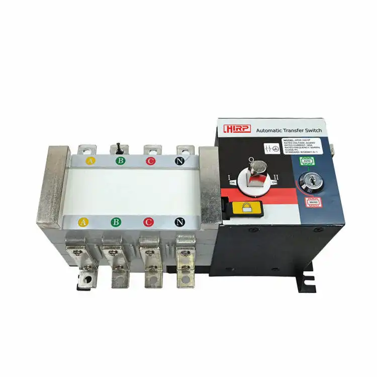
An automatic transfer switch sits between at least two sources and the served load. Its controller checks source voltage and frequency, applies programmed timing, commands a mechanism, and watches position or fault inputs. No power at the load can therefore come from the utility, generator or inverter, the ATS, downstream protection, a control mode, or more than one problem at once. Review how an ATS monitors and transfers sources if the system sequence is unfamiliar.
Use only a closed-door reset explicitly authorized for your role by the exact current manual and site procedure. If the fault returns, the state is unclear, or power does not return through the documented automatic sequence, stop and call qualified service.
The same word is often used for controls that change alarms, logic, timing, or the live power path. Record the exact label and verify the manufacturer’s definition before deciding what it does.
| Action | What it may change | What it does not prove | Publishing-safe rule |
|---|---|---|---|
| Alarm acknowledgement | An annunciator, horn, relay, or visible alarm state. | That the fault is cleared or the ATS can transfer. | Capture the message first. Some faults remain active after acknowledgement. |
| Controller reset | A fault latch or automatic logic on a specific controller. | Source quality, mechanism health, isolation, or downstream power. | Use only the exact closed-door function authorized for the user’s role. |
| Automatic retransfer | The programmed return to the preferred source after it becomes acceptable. | That a visible delay is a fault. | Allow source qualification and configured timing to complete. |
| Manual retransfer | A product-specific operator command to complete a return. | That the same command exists or is permitted on another ATS. | Follow the exact controlled operating procedure; do not copy a button sequence. |
| Time-delay bypass | A deliberate removal of one programmed delay. | That source conditions are healthy or bypass is safe in this event. | Never bypass timing as a generic way to hurry restoration. |
| Manual mechanism or bypass/isolation | The live power path or a maintenance architecture. | That the enclosure, load, or bypass path is deenergized. | Qualified-service control only. It is not an emergency reset shortcut. |
Model-specific manuals from Eaton, Generac, and ASCO distinguish these actions in different ways. Their examples prove why the terms matter; they are not interchangeable field instructions.
Keep people clear and use the site, household, utility, or emergency response plan. Restoring power is never more important than avoiding shock, arc flash, fire, equipment damage, or loss of a critical service.
These signs can indicate a failed connection, insulation damage, or electrical fault.
Stay clear · do not touch or reenergizeMoisture and physical damage can defeat insulation, controls, seals, and terminations.
Arrange qualified inspection firstA lock or tag is an authorization boundary. A missing cover can expose more than one source.
Never remove or bypassRepeated reclosing can reenergize a fault. A reset that fails is diagnostic evidence.
Stop repeated reset attemptsThe outage may require a designated continuity or emergency response, not trial-and-error recovery.
Escalate under the written planAn ATS may be operating correctly while the preferred source is absent, the alternate source is unacceptable, a downstream protective device is open, a configured delay is running, or a controller mode inhibits transfer. Start with evidence visible without opening equipment.
The broader generator transfer switch solution helps explain why the source, ATS, protection, controls, and load must be reviewed as one system.

This sequence describes the information and authority needed before a documented reset. It intentionally does not identify a breaker, button, handle, disconnect, menu, voltage test, or restoration order.
If any red flag exists or a critical load is affected, stop and use the emergency or continuity plan.
Outcome: safe escalation begins first.Capture the exact message, indicators, time, event order, source state, ATS identity, and affected loads before anything changes.
Outcome: the fault history is preserved.Separate normal source, alternate source, ATS/controller, downstream distribution, and intentional timing or mode.
Outcome: the right service channel is identified.Match the installed model and controller revision. Do not use a similar-looking product, old PDF, forum post, or video.
Outcome: the control’s meaning and permitted role are known.Proceed only if the manual and site procedure permit your role, the fault is cleared, and no trip, lockout, or hazard remains.
Outcome: no enclosure opening or forced transfer.Observe the approved interface. Do not bypass source qualification, warmup, cooldown, retransfer timing, or alarm logic.
Outcome: if power or Auto state does not return, stop and call service.An alarm clear and power restoration are different outcomes. Treat the result as evidence instead of proof that the system is fixed.
Utility power may be absent, unstable, or outside the controller’s configured acceptance limits.
Do not assume street power means the ATS has accepted it.Fuel, battery, inverter, controller, overload, or source-quality conditions may block transfer.
A source reset is not automatically an ATS repair.The controller may verify stability, warm up, cool down, or wait before retransfer.
Do not bypass timing to make recovery appear faster.Automatic transfer can be inhibited by a test, maintenance, manual, monitor, or lockout state.
Record it; do not change programming from generic advice.The ATS may be healthy while a feeder, load panel, or branch circuit does not supply the affected load.
A repeated protective trip requires diagnosis before reenergization.Position feedback, mechanism, control, or source-input faults may continue to inhibit output.
If the error returns, preserve it and stop reset attempts.
Some ATSs include a manual operator, bypass-isolation arrangement, drawout mechanism, or maintenance state. Those features can change the live power path and may interrupt loads. Isolating an ATS does not necessarily deenergize the bypass switch, load, enclosure, line side, or control circuits.
Qualified personnel use the exact documentation, written energy-control procedure, applicable code, and an approved test plan. SENTOP can help match a model or document set; field isolation, measurement, repair, and recommissioning belong to authorized local professionals.
Map normal, generator, inverter, battery, UPS, control power, bypass, photovoltaic, and downstream paths that can affect the ATS or load.
Review exact messages, source availability, transfer feedback, alarms, event sequence, settings state, and connected generator or storage records.
Disconnect all relevant sources under the approved procedure and verify absence of voltage, including line-side, alternate, backfeed, stored, and control energy where exposure is possible.
Check source quality, protective devices, mechanism, interlocks, control circuit, enclosure, neutral and grounding design where relevant, and downstream distribution.
Remove the root cause, follow the model-specific test, restore the intended automatic configuration, and confirm the served-load scope and operating limits.
Record the fault, corrective action, tests, final status, settings baseline, recurring symptoms, and preventive recommendation for the next outage.
Do not delay emergency escalation to complete a checklist. When conditions are stable, this evidence helps the right technician arrive with the correct manual, tools, parts, and system context.
ATS make, model, serial, controller, and connected generator, inverter, or storage model from exterior labels or records.
LCD text, code, LEDs, source and load position, Not in Auto, lockout, test, maintenance, alarm, and app message.
Utility loss and return, source start or stop, alarm time, transfer attempt, weather, recent service, and whether it happened before.
Affected rooms, panels, and critical loads; partial power; recent large load; overload; renovation; or load-management change.
Which approved exterior control was used, its result, and whether the same alarm, trip, or operating state returned.
There is no universal test or maintenance interval for every ATS. Use the exact OEM schedule, adopted requirements, system classification, AHJ expectations, and site continuity plan.
Maintain the exact ATS, controller, generator, inverter, and battery manuals; one-line diagram; service contact; and normal-state reference photo.
Record outage timing, alarm text, visible state, approved reset result, corrective action, and whether the condition recurred.
Schedule qualified work under the manufacturer and site procedures. Use the separate guide to plan ATS functional testing; do not turn PNNL’s example checklist into an owner DIY schedule.
Document which medical, security, refrigeration, communications, data, and process loads are served—and what to do if they are not.
SENTOP can help organize an exact-model or replacement-product discussion. This does not replace local fault diagnosis, electrical isolation, repair, commissioning, or approval.
Review the current SENTOP ATS range before requesting exact-model or replacement matching.
Explore automatic transfer switchesPlan source isolation, neutral design, WCR, load management, professional work, and commissioning before field installation.
Read the safety-first ATS installation guideCompare sources, voltage, phase, poles, transition, fault duty, enclosure, controls, and approval inputs.
Open the transfer switch selection guideUse the system-level guide to organize an approved one-line and document handoff—not as permission for live work.
Review the transfer switch wiring guideSee how source, transfer, protection, controls, and priority loads fit a backup-power project.
See generator and standby applicationsPrepare the system data needed for a generator changeover and ATS product discussion.
Review the generator transfer solutionReview available company and product documents, then verify exact-model scope and current status.
Review standards and certificate documentsKeep urgent reset decisions separate from a scheduled, documented, qualified functional-test program.
Plan ATS functional testingThese answers are intentionally model-neutral. The exact current manufacturer manual, site procedure, and qualified local service provider remain authoritative.
These sources support the decision rules and product-specific examples. They do not replace the adopted law, exact product instructions, approved one-line, site procedures, or qualified professional judgment.
Send the exterior nameplate, exact fault text, visible source and position status, system voltage and phase, one-line if available, quantity, and destination. SENTOP can review ATS model and document matching while qualified local service handles field safety and diagnosis.
