
Loose connections on terminal blocks account for roughly 30% of all electrical failures in industrial control panels, according to data compiled by NFPA electrical incident reports. Terminal block failure analysis is the systematic process of identifying why a terminal connection failed—whether through thermal damage, mechanical stress, chemical corrosion, or electrical breakdown—and tracing that failure back to its root cause so it doesn’t happen again. This guide walks you through every failure mode, the exact diagnostic tests that matter, and the preventive strategies that actually keep panels running.
What Terminal Block Failure Analysis Actually Involves
Terminal block failure analysis is the systematic process of identifying how and why a terminal block stopped performing its intended function — then tracing that malfunction back to a definitive root cause. It’s not guesswork. It’s a structured methodology combining visual inspection, electrical testing, material examination, and environmental assessment to produce actionable conclusions.
Why does structure matter here? Because loose connections alone account for roughly 30% of electrical equipment failures in industrial settings, according to data referenced by the NFPA 70B recommended practice for electrical equipment maintenance. Without a repeatable diagnostic framework, technicians often fix the symptom — replacing a charred block — while the actual cause (undertorqued conductors, chemical exposure, vibration fatigue) persists and recurs.
The scope typically covers three phases: failure mode identification (what happened), mechanism determination (how it happened), and root cause isolation (why it happened). Skipping straight to root cause — a common shortcut — almost guarantees you’ll miss contributing factors like creep relaxation in aluminum conductors or galvanic corrosion between dissimilar metals.
A practical tip most manuals won’t tell you: always photograph the failed terminal block in situ before removing it. Orientation, adjacent wiring, and panel position often reveal thermal or mechanical stresses invisible once the block hits your bench.
Effective terminal block failure analysis ultimately protects both equipment uptime and personnel safety — two outcomes no facility can afford to leave to chance.
Common Terminal Block Failure Modes You Need to Recognize
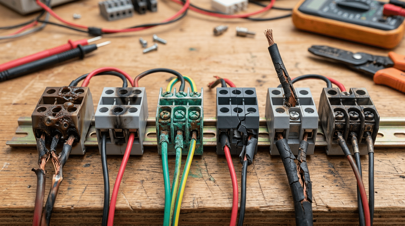
Six failure modes account for the vast majority of terminal block problems in industrial and commercial installations. Recognizing them early — before a nuisance becomes a shutdown — is the core skill behind effective terminal block failure analysis.
| Failure Mode | Telltale Signature | Primary Trigger |
|---|---|---|
| Melting / Heat Damage | Deformed housing, discolored plastic, charred conductors | Overcurrent, loose connections, undersized wire gauge |
| Arcing / Tracking | Carbon traces (tracking paths) on insulation surfaces | Voltage transients, contamination, insufficient creepage distance |
| Corrosion | Green or white oxide deposits on contact surfaces | Moisture ingress, galvanic mismatch between dissimilar metals |
| Mechanical Cracking | Hairline fractures in housing or mounting ears | Over-torque during installation, vibration fatigue, thermal cycling |
| Insulation Breakdown | Reduced dielectric strength, surface pitting | UV exposure, chemical attack, aging polyamide (PA 6.6) |
| Contact Resistance Buildup | Localized hot spots detectable via thermography (ΔT > 10 °C above ambient) | Oxide layer growth, insufficient contact pressure |
Contact resistance buildup is the most insidious because it escalates silently. A NFPA analysis found that electrical distribution and lighting equipment — including terminations — contributed to roughly 34,000 home structure fires per year in the U.S. between 2016 and 2020. Many of those trace back to high-resistance connections that went undetected for months.
Pro tip: During any terminal block failure analysis, always measure contact resistance before disassembly. Once you pull the conductor, you lose the as-found torque and oxidation evidence that tells the real story.
Thermal Failures — Melting, Discoloration, and Heat Damage
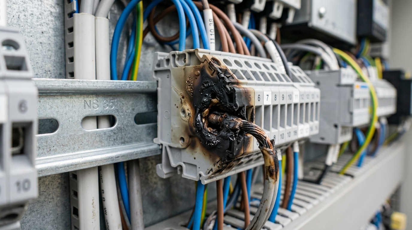
Thermal damage is the single most destructive failure mode you’ll encounter during terminal block failure analysis. The mechanism is straightforward: excessive heat builds at the connection point until the housing material — typically polyamide (PA 6.6) rated to around 130°C continuous use — begins to deform, discolor, or melt entirely. But pinpointing the source of that heat separates a useful diagnosis from guesswork.
Overload-Induced Melting vs. Connection-Resistance Heating
These two causes produce visibly different damage patterns. Overload melting tends to affect the conductor and surrounding housing uniformly, often across multiple adjacent terminals sharing the same circuit. Connection-resistance heating, by contrast, creates localized hot spots — you’ll see discoloration concentrated at one specific termination point while neighboring blocks remain unaffected.
A study referenced by the NFPA found that loose connections can generate temperatures exceeding 300°C — well above the autoignition point of most thermoplastic housings. This is thermal runaway: resistance rises with temperature, which generates more heat, which raises resistance further.
Pro tip: During terminal block failure analysis, check the torque spec first. Under-torqued connections account for a disproportionate share of thermal events. A connection torqued to only 50% of its rated value can see contact resistance increase by 400% or more over months of thermal cycling.
- Brown/amber discoloration: Early-stage overheating, typically 150–200°C exposure
- Black charring with brittle housing: Sustained temperatures above 250°C — investigate connection resistance immediately
- Melted or fused conductors: Usually indicates overcurrent event or dead short downstream
Skip the visual-only assessment. Always pair your inspection with infrared thermography data or micro-ohm contact resistance measurements to confirm whether the root cause is current overload or a degraded mechanical connection.
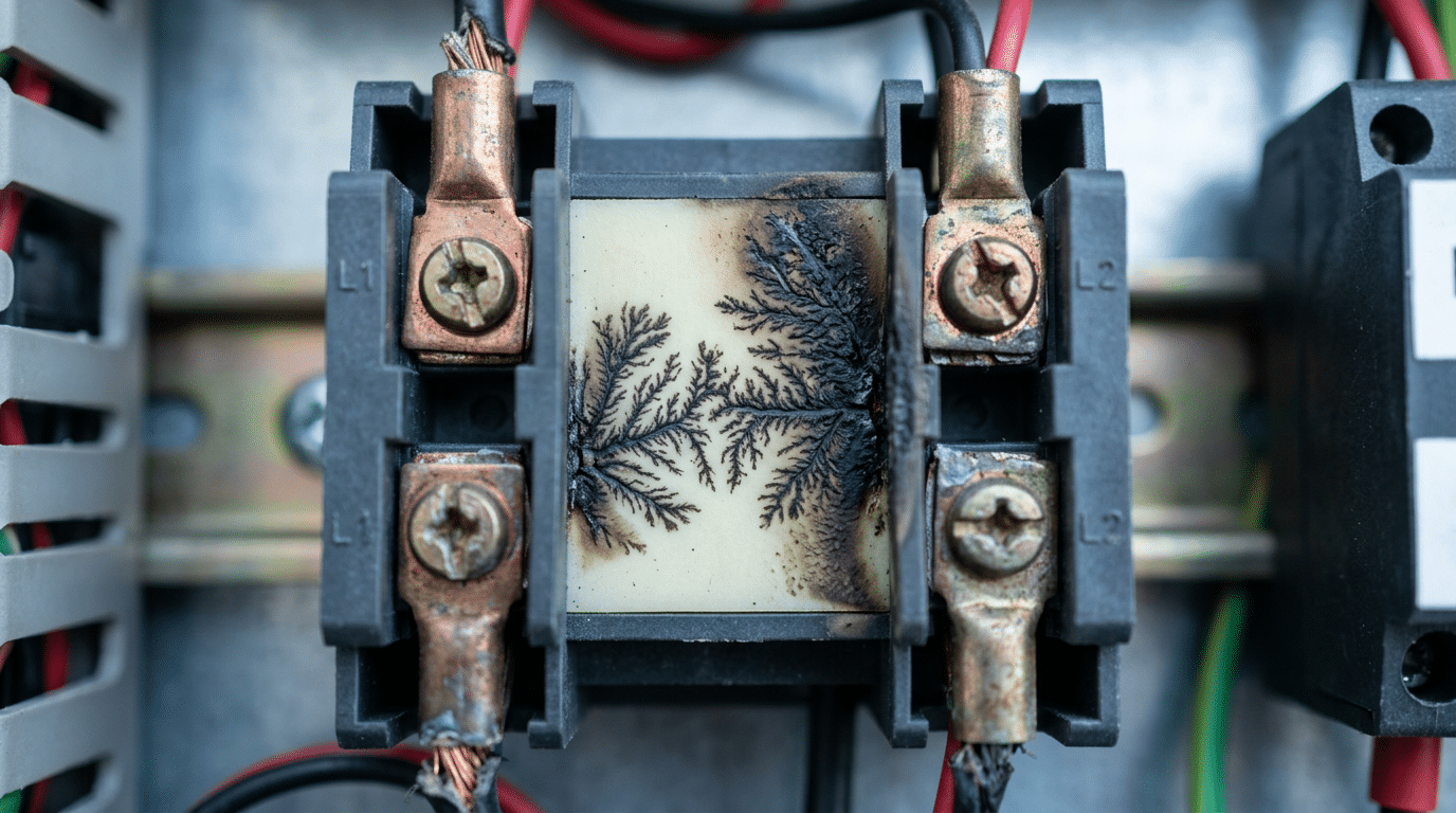
Electrical Failures — Arcing, Tracking, and Dielectric Breakdown
Arcing across terminal block surfaces doesn’t happen spontaneously. It requires a trigger — typically a voltage transient, loose connection, or contamination bridging two conductors. Once an arc initiates, surface temperatures can exceed 6,000°C at the arc point, instantly carbonizing surrounding insulation material and creating a conductive path for future events.
Carbon tracking is the insidious follow-up. Dust, moisture, or industrial residue deposits on the insulating barrier between terminals. When voltage stress is applied, leakage current flows along these contaminated paths, progressively charring the surface. Each micro-discharge deposits more carbon, lowering the surface resistance further. You’ll recognize tracking by dendritic (tree-like) burn patterns etched into the plastic — a hallmark finding during terminal block failure analysis.
Pro tip: Wipe suspect surfaces with isopropyl alcohol before testing insulation resistance. If resistance jumps dramatically after cleaning, contamination-driven tracking is your culprit — not bulk material degradation.
Dielectric breakdown is a different beast. Aging polyamide (PA 6.6) or polycarbonate housings lose dielectric strength over time as UV exposure, thermal cycling, and chemical attack degrade polymer chains. According to IEEE and material science research, nylon-based insulators can lose up to 30% of their original dielectric strength after 10 years of service in harsh environments. When the remaining dielectric strength drops below the working voltage, internal puncture occurs — often with no external warning signs until catastrophic failure.
Effective electrical failure analysis demands you distinguish between surface phenomena (arcing, tracking) and bulk insulation failure (dielectric breakdown), because the corrective actions differ entirely. Surface issues call for environmental controls and cleaning protocols; bulk failure means the terminal block must be replaced.
Environmental and Chemical Failures — Corrosion, Moisture Ingress, and Material Degradation
Galvanic corrosion is the silent killer in terminal block failure analysis. When dissimilar metals — say, a copper conductor seated in a tin-plated steel terminal — are exposed to even trace moisture, an electrochemical cell forms. The less noble metal corrodes preferentially, increasing contact resistance by orders of magnitude before any visible damage appears.
How fast does this happen? In coastal or high-humidity environments (above 60% RH), galvanic corrosion can raise contact resistance by over 300% within 18 months, according to research documented by Wikipedia’s overview of galvanic corrosion. That elevated resistance then triggers the thermal failures covered in Section 3 — a cascading chain many technicians miss.
Chemical Attack on Housing Materials
Polyamide (nylon PA66) housings dominate the market, but they absorb moisture — up to 2.5% by weight at saturation. This absorption weakens dielectric strength and promotes surface tracking. Exposure to sulfuric acid fumes, ammonia, or hydrocarbon solvents accelerates crazing and embrittlement, particularly in wastewater treatment plants and petrochemical facilities.
Practical tip: If you’re specifying terminal blocks for chemically aggressive environments, skip standard PA66. Use ceramic or PPE/PS (polyphenylene ether/polystyrene) housings rated to UL 94 V-0 — they resist hydrolysis far better.
- Condensation cycling — repeated dew point crossings cause micro-pooling inside enclosures, wicking into crimped connections
- Salt spray — accelerates pitting on zinc-plated components; specify stainless steel hardware for IEC 60068-2-52 severity levels
- UV degradation — outdoor-rated blocks need stabilized thermoplastics or metal housings to prevent polymer chain scission
During terminal block failure analysis in outdoor or industrial settings, always swab contact surfaces and test pH. A reading below 5.0 or above 9.0 points directly to chemical attack as a contributing root cause.
Visual Inspection and Initial Diagnostic Steps
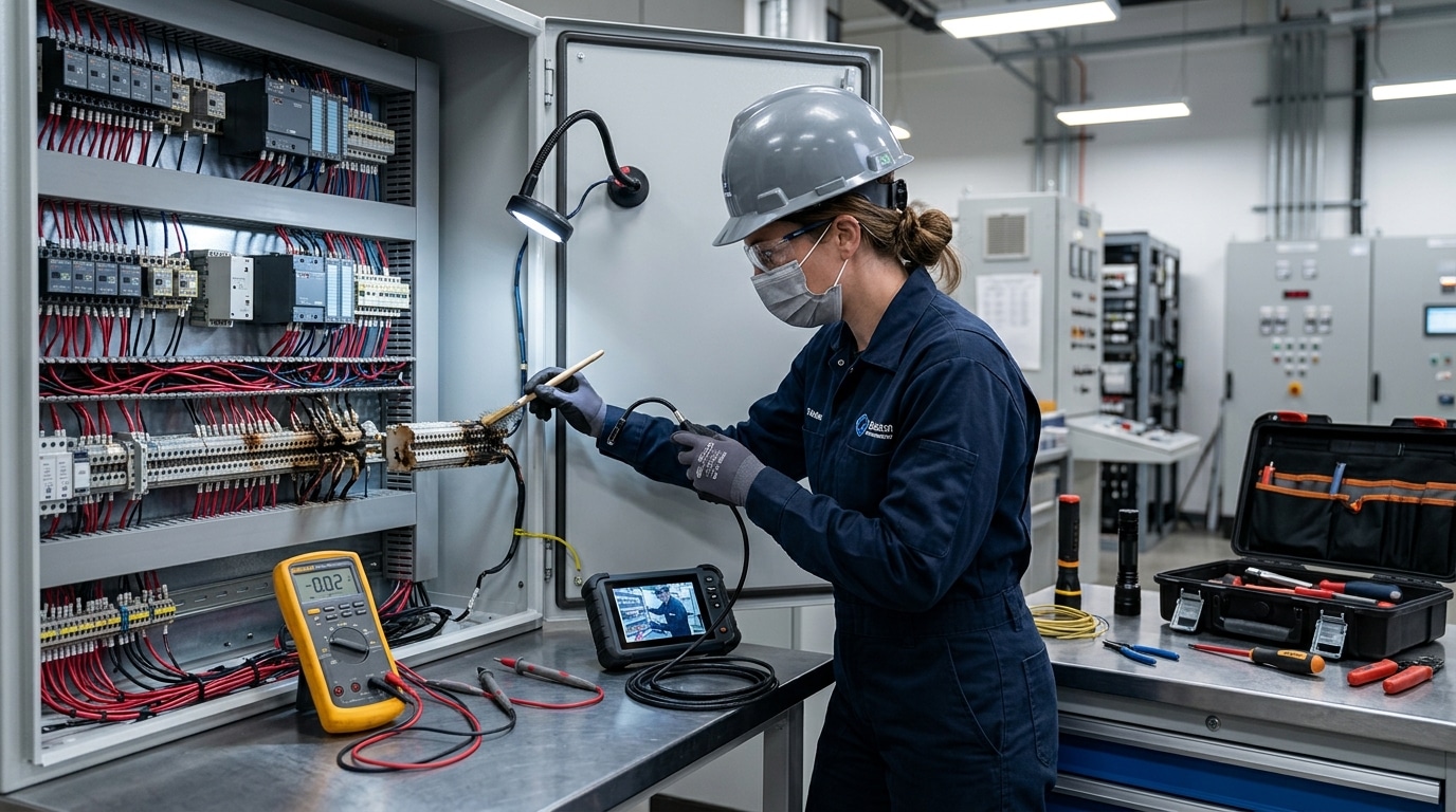
Before you touch a single wire, de-energize the circuit and apply lockout/tagout (LOTO) procedures per OSHA’s Control of Hazardous Energy standard (29 CFR 1910.147). Verify zero energy with a rated voltage tester — not a non-contact pen. According to NFPA 70E, electrical contact accounts for roughly 5% of workplace fatalities in the U.S., so skipping this step isn’t an option.
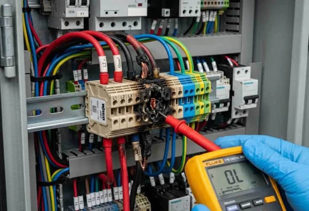
Photograph everything before disturbing the scene. Capture wide-angle shots of the entire panel, then close-ups of each suspect terminal block at multiple angles. Use a macro lens or smartphone macro mode to document carbonization trails, pitting on conductor surfaces, and hairline cracks in the housing. These images become your baseline evidence during terminal block failure analysis.
What to Look For — A Prioritized Checklist
- Burn patterns and discoloration gradients — note whether charring radiates from the conductor entry point or the contact plate. Directional burn marks reveal the origin of thermal runaway.
- Mechanical deformation — warped housings, cracked DIN rail clips, or stripped screw heads indicate overtorque or impact damage.
- Environmental indicators — condensation residue, salt deposits, or fungal growth on adjacent components. Record ambient temperature and humidity with a calibrated hygrometer.
Pro tip: Smell matters. A sharp, acrid odor near a terminal block often signals polyamide (PA 6.6) thermal decomposition — a detail that won’t show up in photos but narrows your failure hypothesis immediately.
Catalog every observation on a standardized inspection form before proceeding to electrical testing. Rushing past this visual phase is the most common mistake in terminal block failure analysis — it contaminates evidence you can never recover.
Electrical Testing Procedures for Diagnosing Faulty Terminal Blocks
Visual inspection flags suspects. Electrical testing convicts them. A structured sequence of measurements transforms your terminal block failure analysis from educated guesswork into quantified diagnosis.
Contact Resistance with a Micro-Ohmmeter
Start here — it catches roughly 80% of degraded connections. A healthy terminal-to-wire junction typically reads below 1 mΩ. Anything above 5 mΩ signals serious trouble: corrosion buildup, insufficient torque, or conductor damage beneath the clamp. Use a four-wire (Kelvin) measurement to eliminate lead resistance from your readings. Compare results against the manufacturer’s datasheet values, not arbitrary thresholds.
Insulation Resistance and Hi-Pot Testing
Apply a megohmmeter at 500 V DC between adjacent terminals and between terminals and the DIN rail. Acceptable insulation resistance for most industrial terminal blocks exceeds 100 MΩ. Values dropping below 10 MΩ indicate moisture ingress or carbonized tracking paths. Hi-pot (dielectric withstand) testing at twice rated voltage plus 1,000 V confirms the insulation hasn’t degraded to the point of imminent breakdown.
Thermal Imaging — The Non-Contact Shortcut
Energize the circuit under normal load and scan with an IR camera. Any terminal running more than 10 °C above its neighbors deserves immediate investigation. Don’t just screenshot the hot spot — record ambient temperature and emissivity settings so your data holds up in a root cause report.
Pro tip: Run continuity checks last, not first. A connection can show continuity at milliamp test currents yet fail catastrophically under full load. Resistance measurements under controlled current reveal what a simple beep test hides.
Root Cause Analysis Methodologies Applied to Terminal Block Failures
You’ve identified the failure mode and confirmed it with electrical testing. Now the real question: why did it happen? Structured root cause analysis (RCA) transforms a single terminal block failure analysis into a corrective action that prevents recurrence across your entire system.
The 5 Whys — Fast and Focused
Start here for straightforward failures. A real-world example: a melted terminal block on a 30A motor circuit.
- Why did the terminal melt? — Excessive heat at the connection point.
- Why was there excessive heat? — Contact resistance measured 850 mΩ, far above the 5 mΩ threshold.
- Why was contact resistance high? — The conductor was loose in the clamping mechanism.
- Why was it loose? — Torque was applied at roughly 0.2 Nm instead of the specified 0.8 Nm.
- Why was incorrect torque applied? — No calibrated torque screwdriver was available; the technician used a standard driver by feel.
Root cause: a tooling and training gap — not a defective terminal block. According to a study of the 5 Whys technique, roughly 68% of industrial failures trace back to human or process factors rather than component defects.
Fishbone Diagrams for Complex Failures
When the 5 Whys leads to multiple branches, switch to an Ishikawa (fishbone) diagram. Map contributing factors across six categories: Man, Machine, Material, Method, Measurement, and Environment. For terminal block failure analysis, “Material” might reveal an incompatible housing polymer, while “Environment” captures ambient temperature excursions that accelerated degradation. The visual structure prevents tunnel vision — a common pitfall when engineers fixate on the most obvious cause and miss systemic contributors.
Pro tip: Always check at least three fishbone branches before concluding your RCA. Single-branch analyses miss contributing causes roughly half the time.
How Installation Errors and Improper Torque Lead to Premature Failure
According to a study referenced by the NFPA, loose connections account for a significant share of electrical failures — and most trace back to a single moment: installation. During terminal block failure analysis, improper torque is the root cause I encounter most frequently, yet it’s the one technicians dismiss fastest.
Under-torqued connections allow micro-movement between the conductor and clamp. That movement creates intermittent contact resistance, which generates heat, which oxidizes the contact surface, which increases resistance further — a runaway loop. Over-torqued connections are equally destructive: they deform the conductor, crack the housing, or damage the clamping mechanism itself. Manufacturers specify torque values (typically 0.5–1.2 Nm for standard DIN rail blocks) for a reason. Use a calibrated torque screwdriver — not “feel.”
Pro tip: Strip wires to the exact length specified on the datasheet. Exposed copper outside the clamp invites arcing; too-short strips reduce contact area by up to 40%.
Mixing wire gauges inside a single terminal is another common installation sin. A 14 AWG conductor paired with an 18 AWG in one clamp means the smaller wire carries almost no clamping force. It will loosen over thermal cycling. If your design requires different gauges, use a distribution block or separate terminals — never compromise.
Equally critical: matching the terminal block’s voltage and current rating to the actual application. Installing a 300V-rated block on a 480V circuit doesn’t just violate NEC requirements — it guarantees dielectric breakdown under transient conditions.
Preventive Maintenance Strategies That Reduce Terminal Block Failures
Reactive repairs cost roughly 3 to 10 times more than scheduled preventive tasks, according to data from the U.S. Department of Energy’s O&M best practices guide. A structured maintenance program built around terminal block failure analysis findings eliminates repeat incidents before they cascade into unplanned downtime.
Torque Re-Checks and Thermographic Surveys
Schedule torque verification at 6-month intervals for standard indoor panels and quarterly for high-vibration or outdoor enclosures. Use a calibrated torque screwdriver — never a standard driver with “feel.” Pair every torque audit with an infrared thermographic scan under at least 40% load. A ΔT exceeding 10°C between adjacent terminals warrants immediate investigation.
Condition-Based Monitoring and Environmental Sealing
- Contact cleaning: Apply manufacturer-approved contact cleaner (not WD-40) to screw-clamp interfaces annually. Spring-cage terminals typically need no cleaning unless corrosion is visible.
- Environmental upgrades: Retrofit IP65-rated enclosure seals and silica gel breathers in coastal or chemical-plant environments. This alone cuts corrosion-related failures dramatically.
- Continuous monitoring: Wireless temperature sensors on critical bus connections provide real-time alerts, shifting your program from calendar-based to condition-based maintenance.
Pro tip: Tag every terminal block with its last inspection date and torque value. This simple habit transforms your terminal block failure analysis from forensic guesswork into data-driven trending.
Documenting and Reporting Your Failure Analysis Findings
A thorough terminal block failure analysis means nothing if the findings disappear into a filing cabinet. Your report serves three distinct audiences: maintenance teams who need actionable fixes, compliance auditors who need evidence trails, and procurement engineers who need data to justify component upgrades. Write for all three.
What Every Failure Analysis Report Must Include
- Photographic evidence: Capture macro and close-up images of the failed terminal block before disassembly. Include a scale reference and label each photo with location, date, and circuit identifier.
- Test data: Record insulation resistance values, contact resistance measurements, and thermal scan results in tabular format with instrument model and calibration date noted.
- Root cause determination: State the failure mechanism (e.g., “resistive heating from under-torqued conductor”) and the contributing factors explicitly. Avoid vague language like “general wear.”
- Corrective and preventive actions (CAPA): Specify exact remedies — torque values, replacement part numbers, revised maintenance intervals — with assigned owners and deadlines.
One detail most engineers skip: documenting the chain of custody for the failed component. If a warranty claim or insurance investigation follows, an unbroken custody record is the difference between a successful and a denied claim. According to ASME standards guidance, roughly 40% of industrial warranty disputes fail due to insufficient failure documentation rather than technical merit.
Pro tip: Store reports in a searchable database — not just PDF archives. Tagging entries by failure mode, terminal block manufacturer, and environment lets you spot recurring patterns across facilities within minutes instead of weeks.
Consistent documentation also feeds your continuous improvement program. When you can pull 18 months of failure data and show that a specific terminal block series fails at 3x the rate of alternatives, you have the evidence to drive real procurement changes — not just opinions.
Frequently Asked Questions About Terminal Block Failure Analysis
What causes terminal blocks to melt?
Excessive current draw through a loose or high-resistance connection generates localized I²R heating. When temperatures exceed the housing material’s glass transition point — roughly 200°C for standard polyamide (PA 6.6) — the block deforms and melts. Overtorqued screws that damage the conductor can produce the same result by reducing effective contact area.
How can I tell if a terminal block needs replacement?
Replace immediately if you observe charring, cracked housings, or measurable resistance above the manufacturer’s spec (typically anything over 5 mΩ for a properly seated connection). Intermittent signal drops or breaker nuisance trips also warrant swap-outs rather than re-tightening.
Can corroded terminal blocks be repaired?
Surface oxidation on copper-alloy contacts can sometimes be cleaned with a non-residue contact cleaner and a brass brush. Deep pitting or galvanic corrosion between dissimilar metals? That’s a replacement scenario — no amount of cleaning restores the original contact geometry.
What tools are needed for terminal block failure analysis?
At minimum: a calibrated digital multimeter, an infrared thermometer or thermal camera, a calibrated torque screwdriver, and a magnifying loupe (10×). For advanced root cause work, a metallurgical microscope and an energy-dispersive X-ray spectroscopy (EDS) system help identify contaminant composition.
How often should terminal blocks be inspected in industrial environments?
NFPA 70B recommends thermographic surveys annually for most industrial panels, with torque re-verification every 1–3 years depending on vibration exposure. High-vibration environments — think compressor rooms or press lines — should move to 6-month intervals. Facilities that adopted this schedule have reported up to a 30% reduction in unplanned electrical downtime.
Key Takeaways for Effective Terminal Block Failure Analysis
Every reliable terminal block failure analysis follows the same three-phase sequence: visual inspection, electrical testing, then root cause determination. Skip a phase, and you risk treating symptoms instead of causes — which means the same failure returns within months.
Facilities that adopt structured failure analysis and preventive maintenance programs reduce unplanned electrical downtime by up to 70%, according to data from the U.S. Department of Energy’s O&M Best Practices Guide.
Here’s your action checklist — print it, laminate it, post it inside every panel:
- De-energize and LOTO before any hands-on inspection.
- Photograph everything — discoloration patterns, arc tracks, corrosion deposits — before disturbing evidence.
- Measure contact resistance with a DLRO; flag any joint exceeding 5 mΩ above baseline.
- Verify torque against manufacturer specs using a calibrated torque screwdriver.
- Apply root cause methodology (5 Whys or fishbone) to trace the failure beyond the obvious symptom.
- Document findings in a standardized report and feed corrective actions into your CMMS.
One often-overlooked practice separates good programs from great ones: trending. Log every failure by mode, location, and terminal block manufacturer. After 12 months, patterns emerge — a specific DIN rail position prone to vibration loosening, a particular terminal series with brittle housings — that no single investigation would reveal. That data transforms reactive troubleshooting into predictive maintenance, which is where the real cost savings live.
See also
Step by Step Guide to Install a Molded Case Circuit Breaker
Systematic Selection of Terminal Blocks for Electrical Panels Made Easy
What are fuses in electrical systems?
How to Test Molded Case Circuit Breakers in 3 Easy Steps

Discover more from SENTOP Electrical Co., Ltd
Subscribe to get the latest posts sent to your email.
