
Short-circuit protection
A breaker, fuse, MPCB or MCP clears severe line-to-line or ground faults within its documented voltage and fault-duty limits.

Select motor protection from the complete motor circuit—not by matching one breaker ampere value to motor power. Start with the nameplate current and real start duty, then verify overload range, magnetic behavior, voltage, poles, available fault current, coordination data, conductors and installation conditions.

“Motor circuit breaker” can describe different products. A thermal-magnetic motor protection circuit breaker (MPCB) may combine adjustable overload and short-circuit protection. A magnetic-only motor circuit protector (MCP) normally needs a separate overload relay. A general MCB or MCCB is not automatically a complete motor-protection solution.
A motor branch circuit is a coordinated chain. Product names vary across IEC, UL/NEMA and manufacturer catalogs, so confirm the actual functions and approvals instead of relying on a label.
A breaker, fuse, MPCB or MCP clears severe line-to-line or ground faults within its documented voltage and fault-duty limits.
A thermal or electronic model reacts to damaging heating from sustained overcurrent, locked rotor or repeated starts.
A contactor or motor controller handles normal remote start/stop and the required utilization duty. Protection does not replace control.
The design must provide the required disconnecting, lockout, emergency-stop and restart behavior under local rules.
Cables, terminals, enclosure heat, busbars and the upstream device affect the final current and short-circuit result.
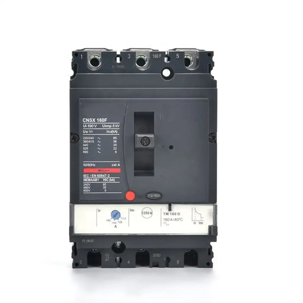
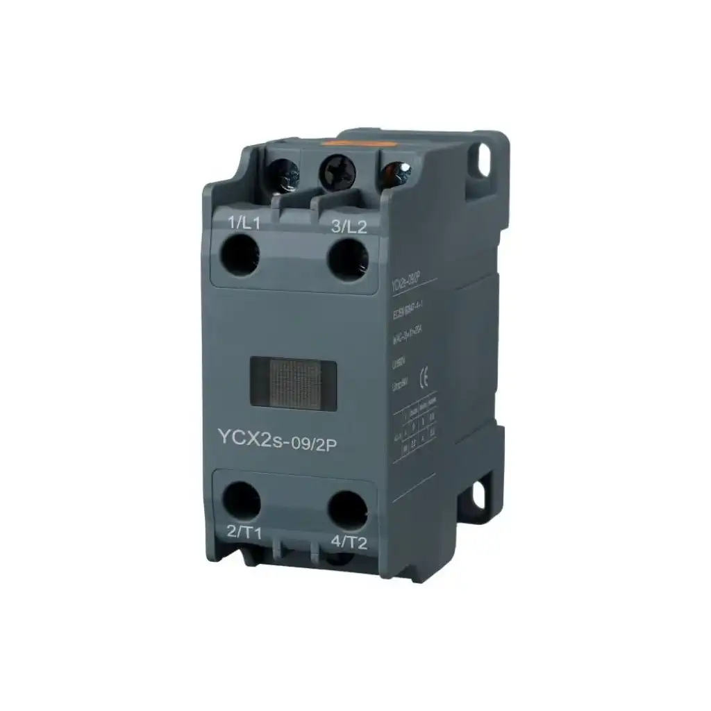
| Architecture | What it can do well | What must still be verified |
|---|---|---|
| Thermal-magnetic MPCB + contactor when needed | Compact adjustable overload and magnetic short-circuit protection; many ranges also provide manual operation and auxiliaries. | Overload range, trip class, phase functions, fault rating, isolation use, contactor coordination, switching duty and market approvals. |
| Magnetic-only MCP + contactor + overload relay | Separates high-fault protection from a flexible overload relay that may add electronics, communication or sensor inputs. | The MCP alone is not overload protection. Use the exact listed or tested combination and setting instructions. |
| MCCB or fuse + contactor + overload relay | Broad current and fault-duty options for larger feeders or published coordination combinations. | A general breaker curve is not automatically motor-optimized; verify start ride-through, conductor protection and assembly rating. |
| VFD or soft starter with approved protection | Controls speed, current or torque during starting and may include electronic motor protection functions. | Follow the drive/starter manual for input protection, bypass, output isolation, multiple motors and stop logic. |
Motors draw a temporary current while they accelerate. The magnitude and duration depend on motor design, supply impedance, mechanical load, inertia and starting method. There is no safe universal multiplier for every motor.
The overload function is intentionally inverse-time: a modest overcurrent is allowed longer than a severe one. The magnetic or instantaneous function reacts much faster to high fault current. Selection must let the real start pass while still clearing a genuine fault within the published curve and coordination limits.
Do not solve nuisance trips by turning settings upward. First check motor voltage/configuration, mechanical load, acceleration time, phase balance, low voltage, enclosure temperature and the selected trip class.
| Starting method | What changes | Protection decision | Common error |
|---|---|---|---|
| Direct-on-line (DOL) | Full supply is applied at start; current and torque can rise sharply. | Check actual acceleration time against the overload and magnetic curves, then use the exact coordination table. | Choosing only from a kW chart without confirming the loaded start. |
| Star-delta | Start topology and current through each device depend on where it is installed. | Use the manufacturer’s wiring and setting table for the exact relay position and Type 1/Type 2 combination. | Applying the same overload setting regardless of line or delta placement. |
| Soft starter | Voltage/torque ramp and bypass arrangement alter current and coordination. | Match the protective device, soft starter and bypass contactor to a published combination. | Copying a DOL breaker selection without checking start limits and bypass duty. |
| Variable-frequency drive | The drive controls current and frequency; its PWM output is not an ordinary supply. | Follow the VFD manual for input protection and any allowed output-side device or multi-motor branch protection. | Using a downstream breaker or contactor for routine start/stop of a running drive output. |
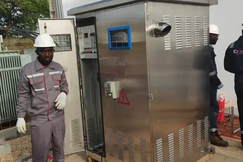
A useful selection sheet combines the motor, driven load, supply, control architecture and installation. Missing one group can produce a breaker that looks correct in a catalog but fails in the machine.
Voltage, phase, frequency, rated current, kW/hp, speed and duty. Use the actual nameplate current as the core running-current input.
Starting method, acceleration time, starts per hour, load inertia and process type: pump, fan, compressor, conveyor, hoist, crusher or other machine.
System voltage, earthing arrangement, source impedance, available fault current and upstream protective device at the installation point.
Manual/remote control, contactor, reversing, star-delta, soft starter, VFD, bypass, emergency stop, interlocks and restart rules.
Cabinet ambient, group mounting, ventilation, altitude, conductor size/material, terminal limits, dust, moisture, vibration and enclosure rating.
Governing code, IEC or North American approach, required coordination/SCCR evidence, certifications, machine standard and target market.
This is a decision sequence, not an ampere formula. A fixed percentage, kW table or frame-size shortcut cannot replace product curves, manufacturer coordination data and the governing electrical rules.
Voltage, efficiency, speed and motor design can change full-load current.
A loaded conveyor can accelerate differently from a lightly loaded fan.
Breaking capacity and SCCR depend on voltage and the full combination.
Ambient heat, grouping and conductor conditions can change thermal performance.
The overload dial, trip class and magnetic pickup do different jobs. Not every motor breaker exposes the same settings, uses the same notation or includes the same phase-protection functions.
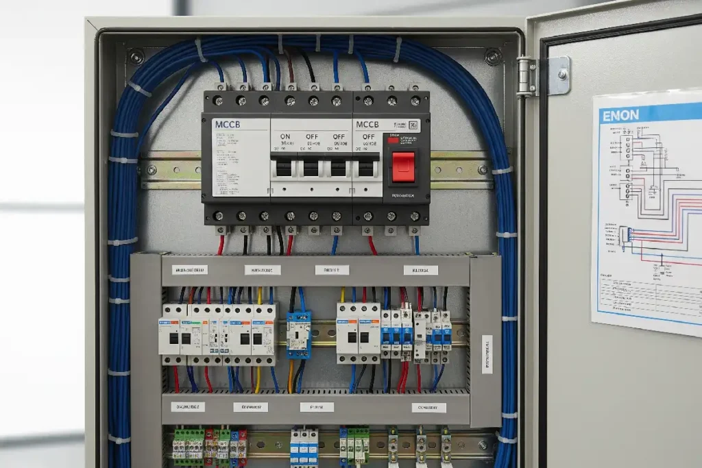
Obtain the available fault current at the installation point. Then verify a documented assembly rating at the actual voltage with the stated breaker/fuse, contactor, overload device, wiring and accessories.
| Term | What it addresses | What the buyer must verify |
|---|---|---|
| Interrupting / breaking capacity | A circuit breaker’s fault-interruption capability under stated standard and test conditions. | Voltage, device reference, applicable standard and all conditions behind the marked/published value. |
| SCCR | Short-circuit current rating of equipment or an assembly in North American practice. | The marked assembly rating must be adequate for the available fault current at the supply terminals. |
| Icu and Ics | IEC ultimate and service short-circuit breaking capacities for a circuit breaker. | Use the exact voltage-dependent data; do not treat Icu and Ics as interchangeable. |
| Conditional short-circuit current / Iq | Capability of a component or combination when protected by a declared short-circuit protective device. | Exact upstream device, setting, contactor/overload combination, voltage and manufacturer table. |
| Type 1 / Type 2 coordination | Tested short-circuit performance of a defined motor-starter combination under IEC 60947-4-1. | The complete bill of materials and fault level. Do not claim Type 2 by mixing individually rated parts. |
Use this as a project checklist. Final selection, installation and energized testing must follow the exact product documentation, local rules and a qualified electrical design review.
Record the nameplate, motor datasheet, driven-load type, expected acceleration, starts per hour, duty and ambient conditions.
Choose manual DOL, MPCB plus contactor, MCP plus overload relay, MCCB/fuse starter, soft starter, VFD, reversing or another arrangement.
Choose a range that includes the required motor-current setting. Match time behavior to the proven start profile and product instructions.
Compare normal starting current/time with the device curve or setting range without weakening documented fault performance.
Check supply system, phase count, AC/DC rating where relevant, frequency and whether the device is approved for the required disconnect/isolation use.
Use exact product references for the protective device, contactor, overload relay, accessories, voltage, motor duty and fault level.
Confirm temperature/grouping derating, enclosure heat, conductors, terminals, torque, orientation, control voltage, auxiliaries and panel rating.
Record settings and references; verify phase sequence, start behavior, loaded current, trip indication, interlocks and required tests before release.
De-energize, lock/tag and verify the de-energized condition before exposed electrical work unless the governing safety rules permit a qualified-person exception. Energized measurements require qualified personnel, suitable instruments, PPE and an approved work procedure. A control button or interlock is not the sole means of isolation.
The goal is to prove that the motor starts, runs and trips as the approved design expects. Keep a controlled record so later maintenance does not turn a known setting into an undocumented dial position.
Device range, catalog reference, overload/FLA setting, trip class, magnetic setting where adjustable and the exact coordination reference.
Acceleration time, current profile when measured, voltage dip, mechanical load and breaker/overload indication.
Compare representative loaded current with the approved motor/application expectation. Investigate overload, friction, unbalance or voltage problems.
Confirm local/remote commands, interlocks, auxiliary contacts, reset inhibition and the safe restart sequence.
Verify torque records, conductor routing, no discoloration, ventilation, deadfronts, labels and safe service access.
Drive outputs, bypasses, reversing duty and multiple motors change the current path, switching duty or protection responsibility. Use the manufacturer’s approved arrangement for each case.
| Application | Selection direction | Do not assume |
|---|---|---|
| VFD, one motor | Follow the drive manual for input protection, motor overload, cabling and any permitted output disconnect. | A standard downstream MPCB is universally compatible or suitable for routine PWM-output switching. |
| VFD, multiple motors | Assess each branch’s overload and isolation needs; use output-side products specifically rated for that configuration. | The drive’s overall current limit fully protects every individual motor branch. |
| Soft starter with bypass | Use published soft-starter, bypass contactor and short-circuit coordination data at the actual voltage and duty. | A DOL breaker selection automatically covers bypass and start conditions. |
| Reversing or plug-reversing | Select contactors, interlocks, protection and utilization ratings for the real reversing duty. | A standard forward-only coordination reference remains valid. |
| Star-delta | Check the exact topology and where each overload element senses current. | The overload setting is identical in line and delta placement. |
“Three-pole 10 A motor breaker” omits the information needed for a compatible quotation. Send a technical package so the supplier can return a specific product combination and its supporting documents.
Do not repeatedly reset or increase a setting until the cause is known. The time and conditions of the trip help separate start-current, overload, phase, thermal and connection problems.
| Symptom | Likely direction | Confirm safely | Corrective direction |
|---|---|---|---|
| Trips immediately at start | Magnetic pickup reached, locked rotor, wrong voltage/configuration, very high inertia or unsuitable start method. | Review motor wiring, mechanical condition and current/time curve using qualified test procedures. | Correct the load or start method and use approved curve/coordination data. Do not defeat protection. |
| Trips after a delay under load | Sustained overload, blocked process, low voltage, high ambient, phase unbalance or incorrect validated setting. | Measure phase current and voltage under representative load; inspect driven equipment and cabinet temperature. | Remove the overload cause, then verify setting, class, motor duty and thermal environment. |
| Motor hums or one phase runs hotter | Phase loss/unbalance, loose terminal, damaged contactor pole, supply issue or motor fault. | De-energize under the approved procedure; inspect connections and measure all phases when permitted. | Repair the supply/control fault and verify phase-protection functions before restart. |
| Breaker or terminals discolor | Loose/unsuitable termination, overload, conductor issue, heat, ventilation problem or damaged device. | Use safe isolation, torque records and approved thermal inspection methods. | Correct conductor, terminal and enclosure defects; replace damaged parts and review derating. |
| Trips recur after reset | The electrical or mechanical fault remains; repeated starts may add thermal stress. | Read the trip cause and inspect after a high-fault interruption as the manufacturer requires. | Correct the root cause and recommission. Do not use repeated resetting as a test method. |
Short answers for common design and purchasing questions.
Select it from the motor nameplate current, voltage, phase, start method, acceleration duty, available fault current and installation conditions. Choose an overload range that includes the required setting, verify magnetic behavior, and use the manufacturer’s coordination table for the exact protective device, contactor, overload function, voltage and fault level. Do not select by kW alone.
An MCB can sometimes be part of an engineered motor circuit, but it is not automatically a complete motor-protection solution. Its curve may not suit the start, and it may not provide adjustable overload protection or the required coordination. Verify each protection function and the governing rules.
Use the motor nameplate, the exact product instructions, the starter design and the governing electrical rules. The adjustment range must include the required value. Do not increase the setting only to stop trips; first investigate current, voltage, load, start time, phase balance, ambient conditions and trip class.
A thermal-magnetic MPCB may provide motor overload protection, so a separate relay may be unnecessary only when the product documentation, control architecture, coordination data and local requirements support that arrangement. A magnetic-only motor circuit protector normally needs a separate approved overload function.
An MPCB usually combines thermal overload and magnetic short-circuit functions. An MCP is commonly a magnetic-only device used with a contactor and overload relay. Catalog terms vary, so confirm the exact functions, approvals and companion devices.
Type 2 coordination is a tested short-circuit performance classification for one specified motor-starter combination under IEC 60947-4-1. It cannot be created by mixing individually rated parts. Check the manufacturer’s table for voltage, fault current, protective device, contactor, overload device and accessories.
Only when both the VFD and protective-device documentation allow that output-side configuration. Some devices are specifically rated for VFD-output multi-motor use, but ordinary downstream switching can damage a running drive. Follow the approved output-protection and stop/control method.
The cause may be a normal but longer-than-expected start, unsuitable magnetic or thermal behavior, low voltage, a seized or heavily loaded machine, a wiring or phase problem, or the wrong setting. Verify the real current/time profile and published curve. Do not disable or arbitrarily increase protection.
Send the motor nameplate, supply voltage, starting method, available fault current, schematic, environment, target approvals, quantity and destination. SENTOP can help organize product matching, supporting low-voltage components, accessories and quotation details for your project.
