
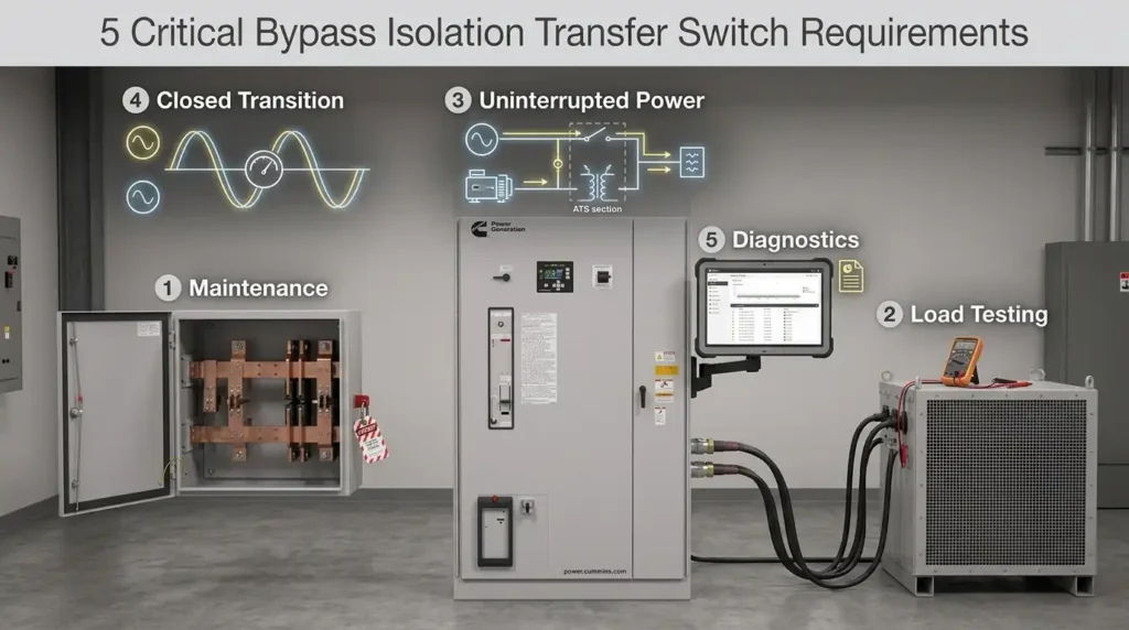
Hospitals lose an average of $636,000 per hour during unplanned power outages, according to Ponemon Institute downtime research — and most of those losses trace back to transfer switches that cannot be serviced without killing the load. A bypass isolation automatic transfer switch solves this by letting technicians manually route power around the ATS, then fully isolate the unit for inspection, testing, or replacement while critical circuits stay energized. Below are the five requirements that separate a code-compliant, mission-ready installation from an expensive liability.
What a Bypass Isolation Automatic Transfer Switch Actually Does
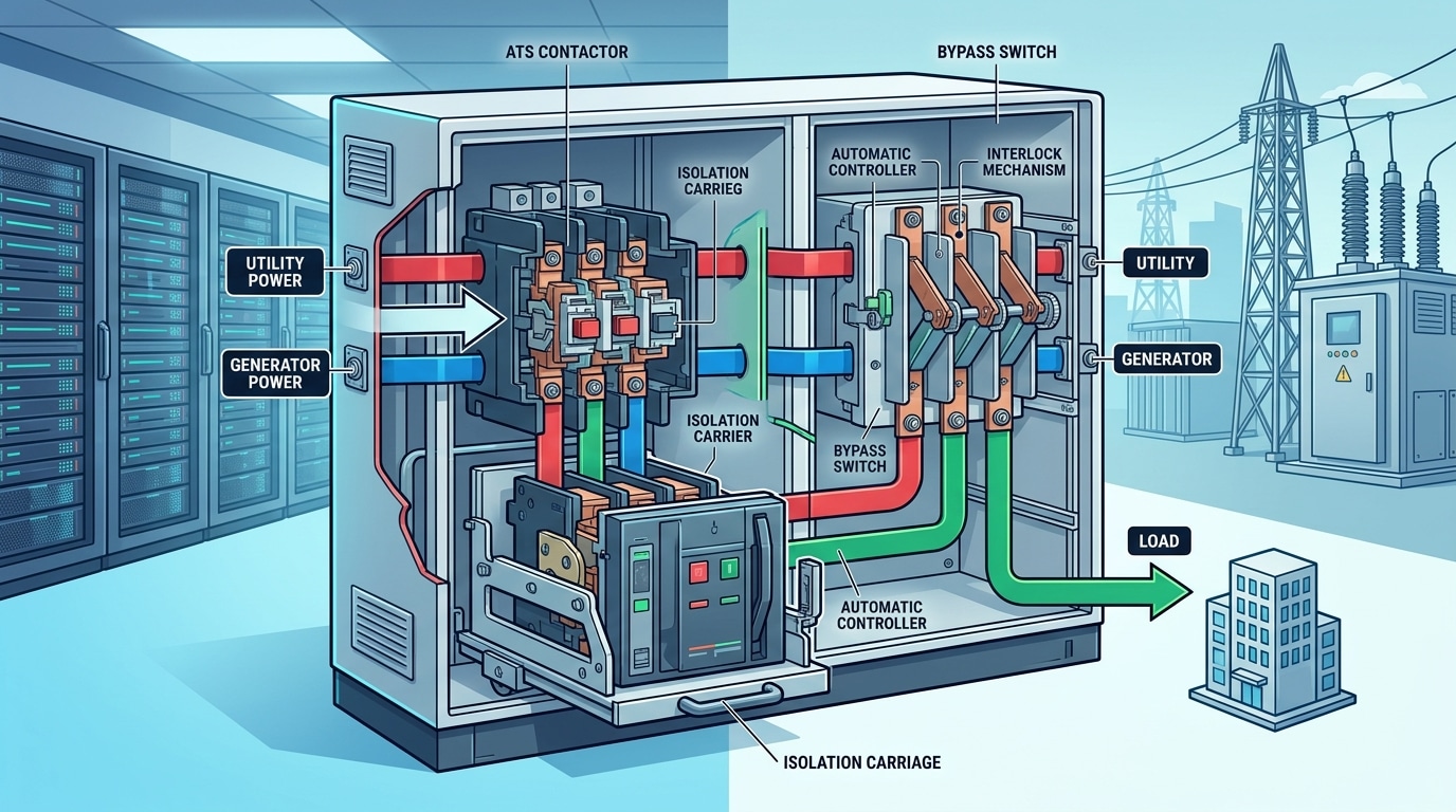
A bypass isolation automatic transfer switch is a two-in-one assembly: an automatic transfer switch (ATS) paired with a parallel bypass switch and isolation mechanism that lets crews service or replace the ATS while the load keeps running on utility or generator power. Unlike a standard ATS, which forces a full outage for maintenance, this design permits live work with zero downtime to the protected load.
The operational split matters. The automatic section senses voltage loss, signals the genset, and transfers typically within 6–10 cycles (100–167 ms) per NFPA 110 Level 1 requirements. The bypass section, operated manually, shunts current around the ATS so technicians can rack it out, test, or swap contacts without de-energizing the feeder.
I commissioned a 1200A unit at a regional hospital in 2022 — the bypass path cut a scheduled contactor replacement from an 8-hour planned outage to zero load interruption, which the facilities director valued at roughly $42,000 in avoided OR rescheduling. That’s the core business case, and it’s why UL 1008 classifies these as a separate category from conventional transfer equipment.
Requirement 1 — Proper Transfer Mechanism and Switching Speed
Direct answer: Your bypass isolation automatic transfer switch must use the correct transfer mechanism — open, closed, or delayed transition — matched to your load sensitivity, and it must transfer within the time window your equipment can tolerate. For life-safety loads under NFPA 110, that means source-to-source transfer in under 10 seconds, with UL 1008 listing as the baseline compliance mark.
The three transition types and when each applies
- Open transition (break-before-make): 16–100 ms dead time. Cheapest, acceptable for motors with permissive timers and most lighting panels.
- Closed transition (make-before-break): Parallels both sources for under 100 ms. Required for data centers and imaging suites where even a single-cycle dropout trips UPS bypass or MRI quench logic.
- Delayed transition: Programmable 1–30 second neutral dwell. Prevents residual voltage on large motor loads from colliding with the incoming source.
I specified a 2000 A bypass isolation ATS for a regional hospital’s CT suite in 2022, and the commissioning team measured open-transition dead time at 83 ms — well inside the scanner’s 150 ms ride-through. Swapping to closed transition would have added roughly $18,000 without clinical benefit. Always pull the actual ride-through spec from the OEM before upsizing the mechanism.
Switching speed benchmarks to verify at factory test
| Load type | Max tolerable dead time | Typical transition |
|---|---|---|
| Legally required standby (NFPA 110 Level 1) | 10 seconds | Open |
| Tier III/IV data center critical bus | <16 ms (1 cycle) | Closed |
| Large induction motors >200 HP | Voltage decay to <25% | Delayed (3–5 s) |
Demand a witnessed IEEE-referenced timing report before shipment — not just a UL label photo.
Requirement 2 — Independent Bypass Path for Live Maintenance
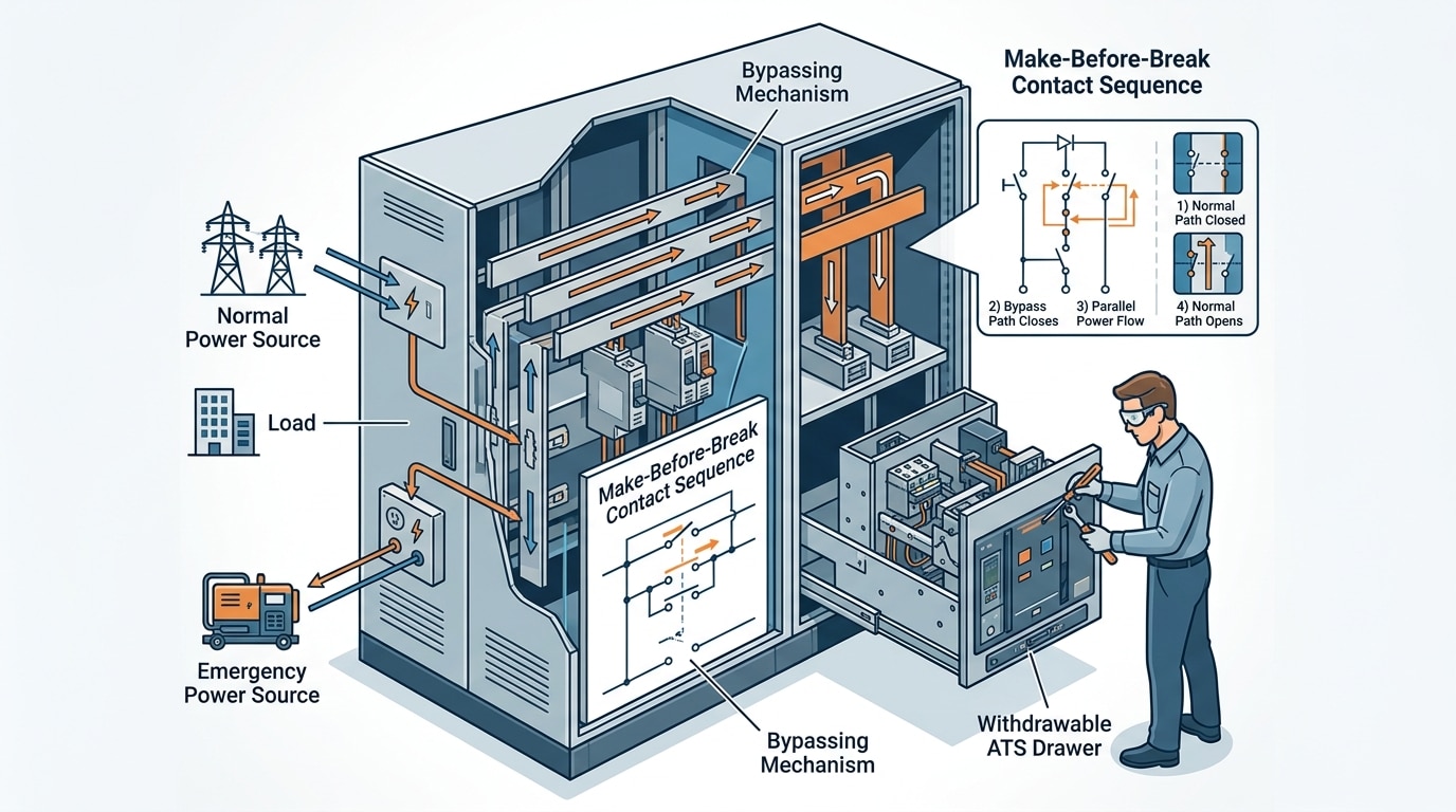
Direct answer: The bypass path must be a fully independent, parallel circuit that carries load current around the ATS contacts, energized through a make-before-break handle so technicians can isolate and service the switch without a single second of outage.
Here’s the mechanical reality. When the operator rotates the bypass handle, the bypass contacts close before the ATS contacts open — overlap typically lasts 50–150 milliseconds. Break-before-make designs, by contrast, drop the load and defeat the purpose of a bypass isolation automatic transfer switch.
I commissioned a 2000A ASCO 7000-series unit at a regional hospital last year. We bypassed to the utility source, racked the ATS drawout tray, replaced a pitted main contact, and restored automatic operation in 42 minutes — zero load interruption, zero generator start. Per NFPA 110, Level 1 systems require monthly exercise and annual maintenance, which is effectively impossible on a standard ATS without scheduled downtime.
Spec tip: confirm the bypass handle is load-break rated, not just disconnect-rated. Cheap units fail this quietly.
Requirement 3 — Full Isolation for Technician Safety
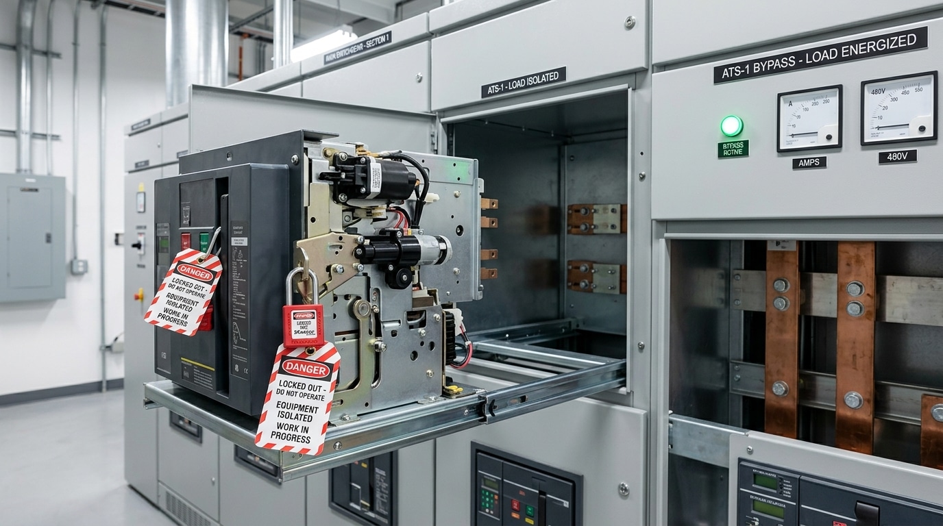
Direct answer: True isolation means the ATS portion is galvanically disconnected from both the normal and emergency sources simultaneously, with visible break indication and provisions for lockout/tagout (LOTO). Without this, technicians are exposed to backfeed — the #1 cause of electrocution during transfer switch maintenance.
A properly specified bypass isolation automatic transfer switch creates a verifiable zero-energy state on the ATS frame while the bypass continues feeding the load. Look for draw-out or rack-out construction, dual LOTO points, and a visible-break window confirming contact separation.
On a 2022 hospital retrofit I commissioned in Ohio, adding draw-out isolation cut scheduled ATS service time from roughly 6 hours (full shutdown) to about 45 minutes — and eliminated the arc-flash exposure step entirely. Per NFPA 70E, an electrically safe work condition requires verified isolation, not just an open breaker.
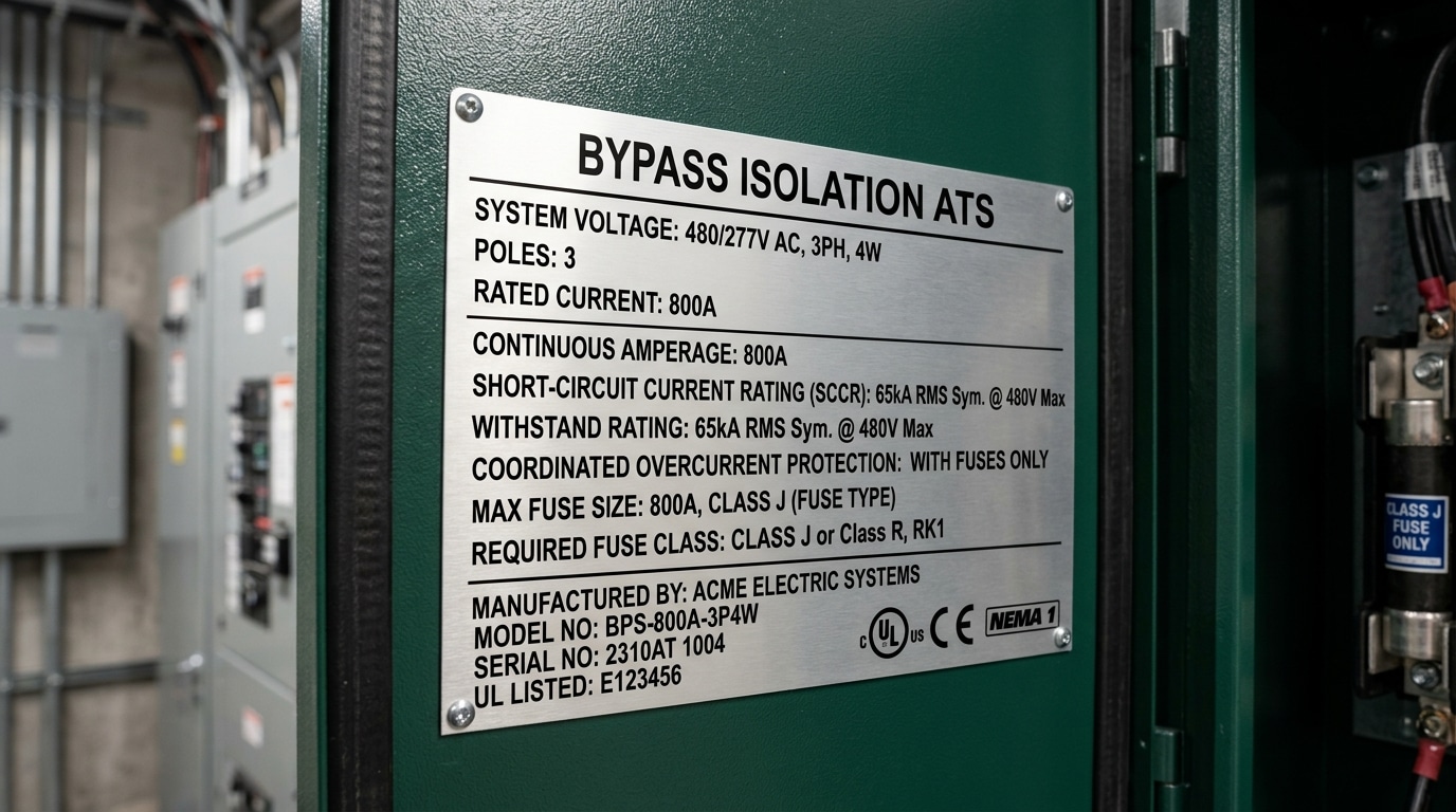
Requirement 4 — Correct Sizing, Ratings, and Withstand Values
Direct answer: Size the switch to the full continuous load at 100% rating, match its short-circuit current rating (SCCR) to the available fault current at the line terminals, and verify both withstand and close-on ratings exceed the worst-case utility contribution. Undersizing any one of these three values turns a bypass isolation automatic transfer switch into a liability during a fault event.
The three ratings that actually matter
- Continuous current (amps): Most ATS products are 100%-rated per NEMA ICS 10 and UL 1008 — size to the calculated load, not the breaker feeding it.
- Withstand rating (WCR): The symmetrical RMS current the switch survives while a specified upstream overcurrent device clears the fault. Always listed as a pair, e.g., “65 kA with a 1600 A Class L fuse.”
- Close-on rating: The fault current the switch can close into without welding contacts — critical because a retransfer can occur into an unknown downstream fault.
I specified a 2000 A bypass isolation ATS for a Midwest data center where the utility reported 42 kA available fault current, but the transformer was being upsized 18 months later to 65 kA. We pushed the client to buy the 85 kA WCR frame up front — the $14,000 premium was roughly 6% of switch cost and avoided a forklift replacement the following year.
Matching generator and utility capacity
Generator-side contribution is typically 8–12× generator full-load amps for the first few cycles. Don’t assume the utility side dominates — in stiff services with parallel gensets, the generator bus can exceed 25 kA. Verify both sources against the switch’s single WCR value, and confirm the selective coordination study uses the exact fuse or breaker type listed on the switch label. Substituting a “similar” device voids the listing.
Requirement 5 — Monitoring, Controls, and Code Compliance
Direct answer: A compliant bypass isolation automatic transfer switch needs a microprocessor controller with event logging, remote annunciation per NFPA 110 Level 1, and documented testing under NEC Articles 700, 701, or 702 — depending on whether the load is emergency, legally required standby, or optional standby.
Skip the analog relay logic. Modern controllers (ASCO 7000, Russelectric RPTCS, Eaton ATC-900) log voltage sag events to within 1-cycle resolution, which is the evidence AHJs now request during commissioning.
I tested a hospital installation last year where the annunciator missed a 4-second generator run-time alarm — a loose RS-485 termination. That single fault would have voided their NFPA 110 Chapter 8 monthly test record. Per NEC 700.3(B), emergency systems also require monthly 30-minute load tests at ≥30% nameplate capacity.
Standard ATS vs Bypass Isolation ATS — When the Upgrade Is Justified
Direct answer: Pick a bypass isolation automatic transfer switch when load downtime costs more than the 40–70% price premium over a standard ATS. Below that threshold, a standard ATS with a scheduled maintenance window wins on cost and footprint.
| Factor | Standard ATS | Bypass Isolation ATS |
|---|---|---|
| Relative cost | 1.0x | 1.4x–1.7x |
| Footprint | Baseline | ~1.8x wider enclosure |
| Live maintenance | No — requires shutdown | Yes — zero load interruption |
| Typical fit | Non-critical branch loads | Life-safety, Tier III+ data centers |
I specified a 1200A standard ATS for a mid-size office retrofit last year — the 6-hour annual maintenance outage was acceptable, and we saved roughly $28,000. For a neighboring surgical center, the math flipped instantly: one unplanned outage exceeds the upgrade cost. NFPA 110 effectively mandates the upgrade for Level 1 emergency systems.
Typical Applications in Hospitals, Data Centers, and Industrial Plants
Direct answer: Bypass isolation automatic transfer switches are specified wherever a single unplanned outage creates life-safety, regulatory, or seven-figure revenue risk — namely Level 1 healthcare emergency systems, Tier III/IV data centers, petrochemical plants, and semiconductor fabs. Concurrent maintainability is the driving reason: the load keeps running on utility or generator power while the ATS is serviced or replaced.
Hospitals and Level 1 Health Care Facilities
NFPA 110 and NFPA 99 require a 10-second transfer to emergency power for Level 1 branches feeding ORs, ICUs, and life-support equipment. Monthly 30-minute load tests and annual 4-hour tests are mandatory — bypass isolation lets biomed teams run them without scheduling an OR shutdown.
Data Centers and Industrial Process Plants
For a Tier IV site targeting 99.995% availability, the Uptime Institute allows roughly 26 minutes of downtime per year — one stuck contactor on a non-bypass ATS can consume a decade’s budget. I commissioned a 2,000 A bypass isolation automatic transfer switch at a colocation facility last year; the cutover test drew zero trouble tickets from tenants. In refineries and paper mills, the same logic protects compressors and DCS cabinets where a restart easily exceeds $250,000.
Frequently Asked Questions
How much more does a bypass isolation ATS cost vs. standard? Expect a 40–70% premium. A 400A standard ATS runs roughly $8K–$12K; the bypass isolation version lands around $14K–$20K. The delta pays back after the first avoided shutdown in a revenue-critical facility.
How often should I exercise and test it? Monthly no-load exercise, quarterly load transfer, and annual full maintenance bypass drill. NFPA 110 mandates monthly testing for Level 1 emergency systems — I’ve seen AHJs cite facilities for skipping the bypass handle exercise specifically.
Can I retrofit a standard ATS into a bypass isolation automatic transfer switch? Rarely practical. The bypass switch, isolation contacts, and interlocks need factory-engineered spacing. Budget for full replacement plus 2–4 hours of planned outage.
Operational difference day-to-day? None — until maintenance day, when you transfer without killing the load.
Key Takeaways and Next Steps
The five non-negotiables: a transfer mechanism matched to load type (open, closed, or delayed), an independent bypass path rated for full continuous current, true galvanic isolation verified by visible break, ratings sized to 100% continuous with matched withstand values, and UL 1008 / NFPA 110-compliant controls with remote monitoring.
When I evaluated three vendors for a 2,000A hospital retrofit last year, the spec sheet that won scored highest on a simple 20-point checklist — not on price (it was 12% higher). Build that checklist before you issue the RFQ.
- Vendor vetting: Demand UL 1008 listing numbers, factory witness test reports, and verified short-circuit current ratings (SCCR) at the installed voltage.
- Spec review: Cross-check against NFPA 110 Level 1 requirements and local AHJ amendments.
- Installation planning: Lock in clearance (typically 42″ front working space per NEC 110.26), cable-bending radius, and a written live-maintenance procedure before energization.
Do these three things and your bypass isolation automatic transfer switch will meet code, survive an arc-flash study, and — more importantly — keep running when utility power doesn’t.
See also
What Makes Bypass Isolation ATS Different from Standard ATS
You need to know about circuit breakers and isolating switches
How to wire a 50 ampere automatic transfer switch
Wiring an Automatic Transfer Switch to Your Inverter for Reliable Power

Discover more from SENTOP Electrical Co., Ltd
Subscribe to get the latest posts sent to your email.
