
Electrical symbols are the “universal language” of electrical engineering, and understanding these symbols is crucial for designing circuits, installing equipment, and debugging. Electrical symbols will greatly help ensure that the completion of specific tasks can cross geographical and linguistic boundaries and be conveyed more quickly. Continue reading this guide to learn about electrical symbols.
What is an electrical symbol?
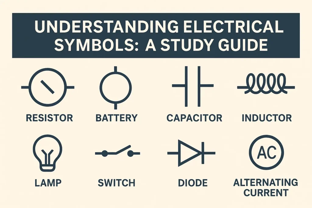
Electrical symbols are standardized visual symbols used in circuit diagrams to represent electrical systems, components, and their interconnects. The symbols represent the function or operation of electrical systems graphically abstractly without the need for verbose text descriptions and enable circuit designers to convey significant information about circuits more efficiently.
Each symbol represents the operation of a specific component or function in a circuit, for example, a resistor symbol represents the function of a resistor in a circuit, while a capacitor symbol represents its function of storing charge. Through these symbols, complex circuit designs become simpler and easier to understand, ensuring smooth operation of the design, analysis, and debugging processes.
Why are electrical symbols important
Electrical symbols can succinctly and clearly depict complex electrical designs. These symbols have universality. Anyone from any country can easily interpret these charts without worrying about language barriers.
At the same time, electrical symbols make the visual complexity of circuits easier and reduce the degree of confusion caused by textual representations when processing equipment. In addition, knowledge of electrical symbols can help engineers easily track faulty equipment and perform appropriate repairs.
Key electrical symbols in circuit diagrams
Circuit diagrams are used to virtually depict symbols used in electronic circuits. Each circuit uses standardized symbols to represent its various parts.
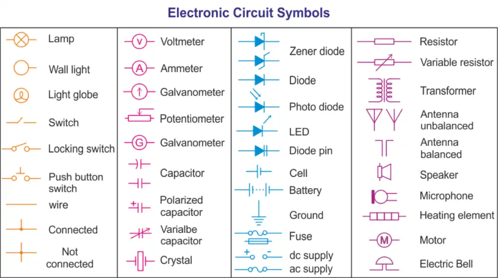
(Source: Circuit Symbols: Key to Understanding Electrical and Electronic Diagrams)
Simple explanation of electrical symbols
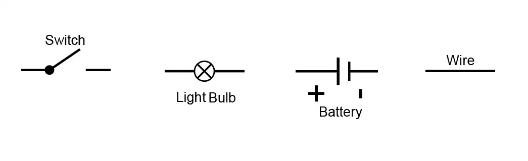
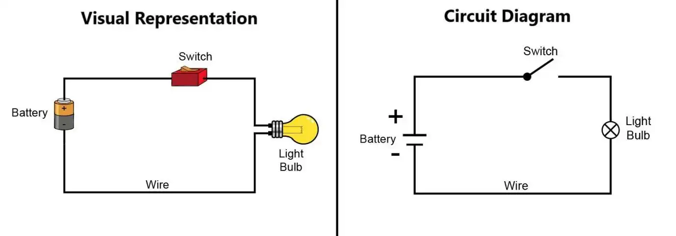
Switch: The above switch symbol represents the closing and opening of circuit connections in a circuit, so this symbol is universally applicable.
Light bulb: The light bulb is resistive and emits light when heated. The symbol for the light source here has a cross mark, indicating that the light comes from a resistive source.
Battery: It is an energy source composed of battery cells containing chemical electrolytes that can provide polarity. The battery cell is represented by two parallel non-uniform lines, marked with positive and negative poles in the battery symbol.
Wire: It is just a connecting conductor between two devices, so for the connection, it is only represented by a straight line.
There are also some other complex symbols that are difficult to interpret without component knowledge. If you have any needs, you can leave a comment and I can introduce them to you separately
Classification of Electrical Symbols
Electrical symbols can usually be classified according to their applications and functions. Here are some common classification methods:
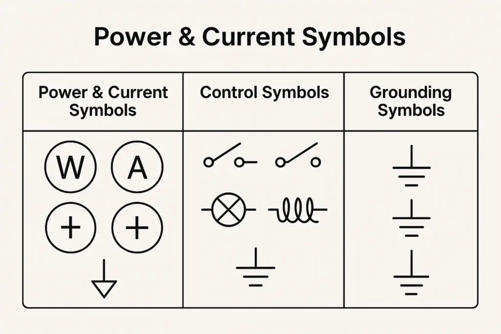
Power and current symbols
These symbols are mainly used to represent devices such as power supplies, loads, switches, circuit breakers, etc. For example, battery symbols, generator symbols, and motor symbols are common symbols in power systems.
control symbol
Control symbols are used to represent components in automation control systems, such as relays, switches, buttons, etc. These symbols help designers create accurate control circuits.
ground symbol
Grounding is a very important part of electrical systems, and the grounding symbol is used to indicate grounding devices, grounding lines, etc. These symbols help ensure the safety and electrical protection of the system.
Standards and specifications for electrical symbols
There are strict requirements and regulations for the use of electrical symbols around the world. The consistency and universality of symbols have standards, and there are two common standard rules.
IEC standards
The International Electrotechnical Commission (IEC) has developed electrical symbol standards to give them the same meaning in different countries and regions. IEC standards have universal applications in electrical design, installation, and maintenance.
ANSI and IEEE symbol standards
In the United States, ANSI (American National Standards Institute) and IEEE (Institute of Electrical and Electronics Engineers) have also developed symbol standards. Although these standards are similar to IEC, they have also been appropriately adjusted according to the specific needs of the United States.
How do circuit symbols form a circuit diagram?
Electronic circuit symbols are concise graphics or pictograms used to describe various components in circuit schematics. In this class diagram, electrical components typically have two or more terminals for connecting the components. Basic electrical and electronic symbols include grounding electrodes, batteries, and resistors. These symbols help to represent even the most complex circuits. With these basic symbols, anyone can draw a circuit diagram. For example, a basic circuit consists of a battery, a switch, and a light bulb connected in a closed loop.
The Application of Electrical Symbols in Circuit Diagrams
Electrical symbols are not just symbols, they represent actual electrical devices and systems. Circuit diagrams use the symbols to graphically illustrate the connection methods, working principles, and control logic of electrical equipment.
- The basic composition of a circuit diagram
A circuit diagram will typically consist of components such as power supply, load, switches, and protective devices. Each part is represented by some electrical symbols, from which the technicians can readily understand the operation of the circuit. - Proper understanding and usage of symbols
The correct method of reading electrical symbols is the foundation of electrical system design and equipment repair. Designers are required to follow standards for proper use of symbols to avoid electrical faults and malfunction.
FAQ
Why do the symbol standards differ?
The electrical symbol standards can be different in various countries and regions. The reason is that there can be variations in the shape and usage of electrical systems. Nevertheless, with the progress of globalization, increasingly countries have used international standards (e.g., IEC) for ensuring symbol uniformity.
How to use symbols in design?
In electric design, symbols need to be used according to standards. Designers should understand the meaning of each symbol and choose the appropriate symbol according to the requirements of the electric system. Symbols need to be brief, simple, and adhere to circuit design requirements.
Read the following article for more information:
Detailed explanation of electrical symbols for circuit breakers
Electronic vs Thermal Magnetic Molded Case Circuit Breaker
How to choose a residual current circuit breaker manufacturer

