
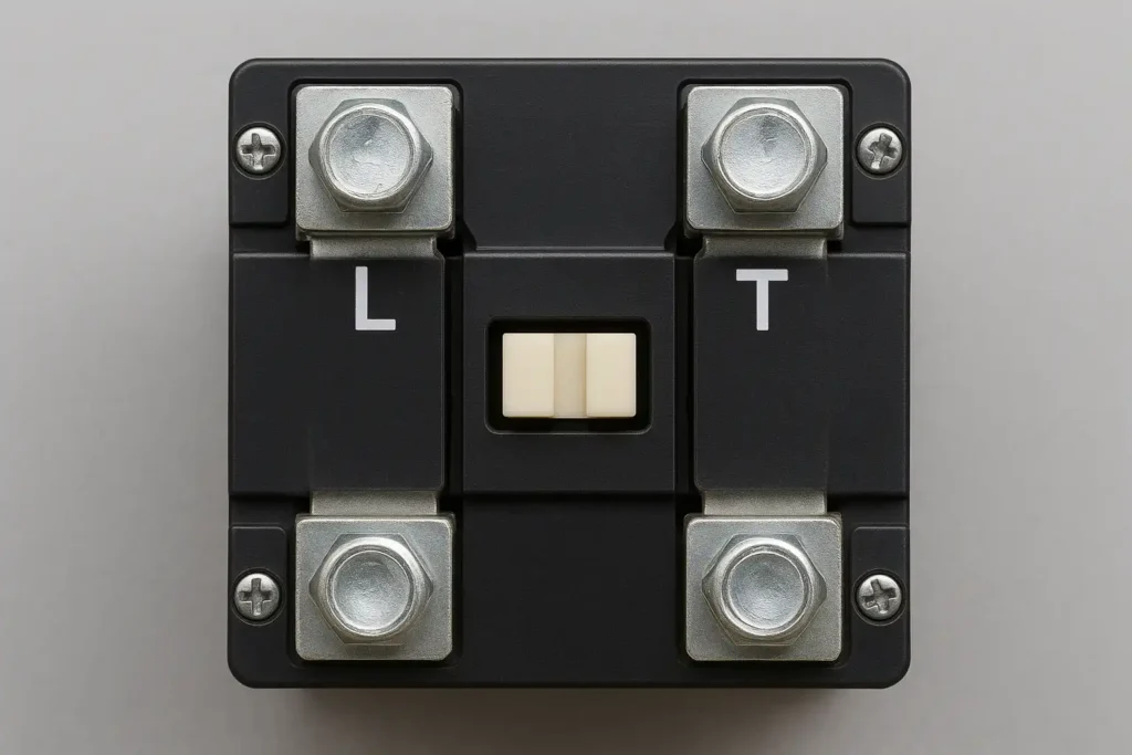
A terminal of contactor is where electrical circuits connect together. The L terminals, or “line terminals,” bring in the power supply. The T terminals, or “load terminals,” send power to the device or circuit.
These terminals of contactor are important for safely controlling electricity flow. Knowing their purpose helps prevent wiring mistakes and keeps things working well. This knowledge also protects devices and lowers the risk of electrical problems.
Understanding L and T terminals of contactor is key for safe electrical setups.
Key Takeaways
-
L terminals bring electricity into the contactor. They connect to the main power source and must be wired properly so the contactor works.
-
T terminals send electricity to devices or circuits. They only have power when the contactor is on, so correct wiring is important for safety.
-
Always follow the wiring instructions from the manufacturer. This avoids mistakes that could damage equipment or cause danger.
-
Check the wiring and connections of L and T terminals often. Finding problems early can stop expensive repairs and keep things safe.
-
If you are unsure about wiring, ask a professional. Complicated setups may need expert help to stay safe and work correctly.
Understanding the Terminal of a Contactor
What Are L Terminals on a Contactor?
L terminals, called line terminals, connect the power supply to the contactor. These terminals take in electricity from the main source. They are the input side of the contactor. If L terminals are not wired correctly, the contactor will not work.
L terminals have specific technical details that explain their use. For example:
|
Specification |
Description |
|---|---|
|
Shows insulation voltage details |
|
|
Adjustment Range of Setting Current [A] |
Range for current adjustments |
|
Rated Operating Current [A] |
Current ratings for AC and DC loads |
|
Function |
Info about covers and easier wiring |
These details ensure L terminals handle electricity safely. Follow the manufacturer’s instructions when wiring them. This prevents problems like overheating or short circuits.
What Are T Terminals on a Contactor?
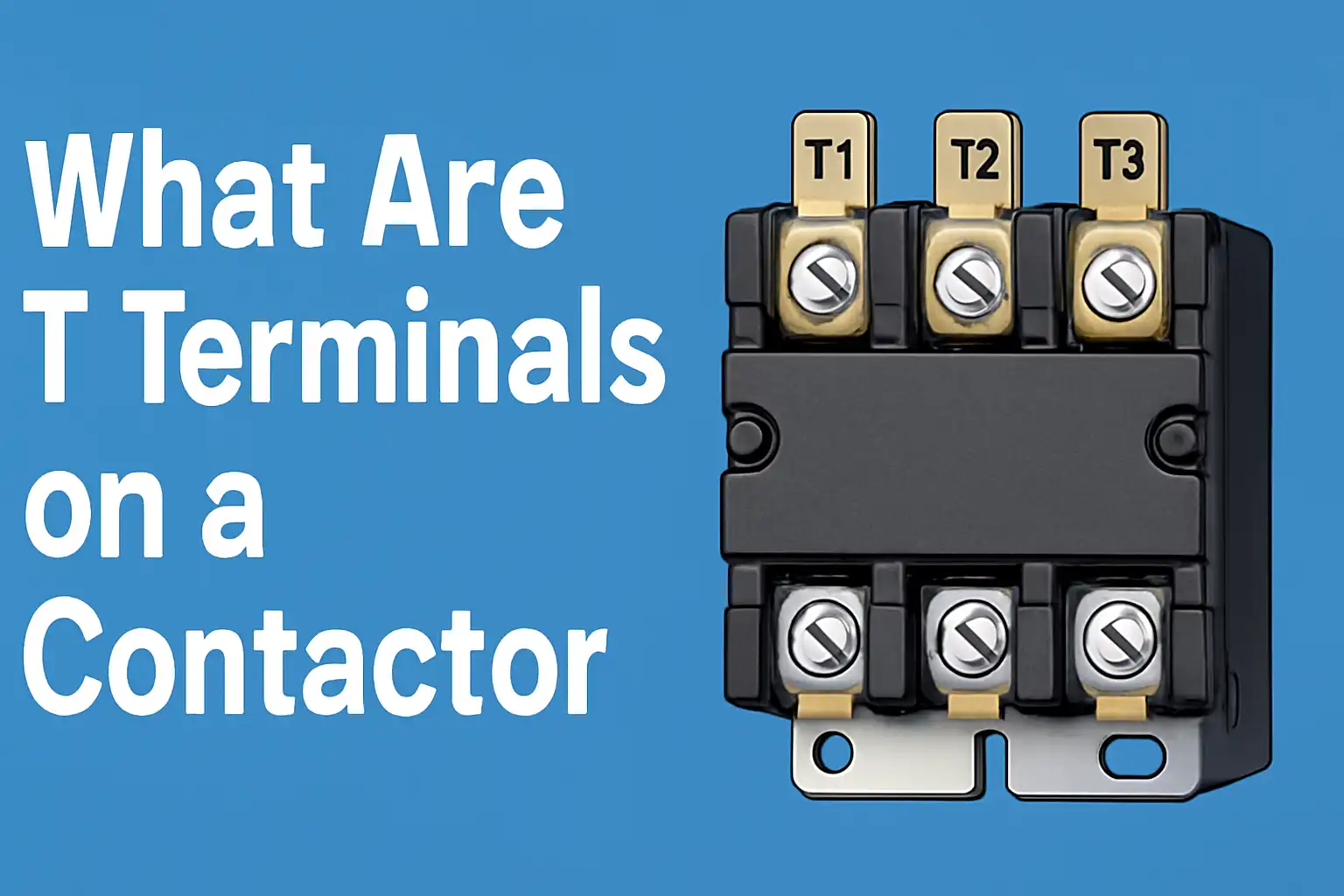
T terminals, or load terminals, send power to devices or circuits. When the contactor is active, T terminals let electricity flow to the load. This powers equipment like motors, lights, or heaters.
T terminals are important for proper current flow. For example:
-
T1 and T2 are output terminals for single-phase systems.
-
They connect directly to the device needing power.
-
Correct wiring of T terminals stops equipment failure and ensures smooth operation.
Knowing how T terminals work helps keep your electrical system safe and working well.
Key Differences Between L and T Terminals
L and T terminals are part of the same contactor but do different jobs. Here are the main differences:
-
Function: L terminals bring in power; T terminals send power out.
-
Position: L terminals are on the input side; T terminals are on the output side.
-
Operation: L terminals always have power if the supply is active. T terminals only have power when the contactor is working.
Tip: Check L and T terminal wiring carefully. Wrong connections can cause safety risks or damage equipment.
Understanding these differences helps you wire a contactor correctly and avoid mistakes.
How L and T Terminals Work in a Contactor
Power Flow Through L and T Terminals
Electricity starts at the L terminals in a contactor. These terminals bring power from the main supply into the system. When the contactor’s coil gets power, it makes a magnetic field. This field pulls the contacts inside together, closing the circuit. At this point, the L terminals connect to the T terminals, letting electricity flow to the load.
The T terminals, or load terminals, send power to the connected device. For example, in a motor system, the T terminals provide the current needed to start and run the motor. If the L and T terminals are not wired correctly, the power flow will stop, and the system won’t work.
Tip: Always check the wiring between L and T terminals to avoid problems and protect equipment.
Role of L and T Terminals in a Single-Pole Contactor
In a single-pole contactor, L and T terminals have specific jobs. The L terminals, labeled L1, L2, and L3 in three-phase systems, connect to the power source. The T terminals, labeled T1, T2, and T3, connect to the device needing power.
Here’s how they work in a single-pole contactor:
-
L terminals bring power from the main supply.
-
The contactor’s coil gets power when the control circuit turns on.
-
This creates a magnetic pull, closing the internal contacts.
-
Closed contacts link L terminals to T terminals, sending power to the load.
This setup ensures the load only gets power when the contactor is active. It also safely controls high-power devices using a low-power circuit.
Examples of Applications in Electrical Systems
L and T terminals are used in many electrical systems. They are important for controlling power flow. Common examples include:
-
Motor Starters: L terminals bring power in, and T terminals send it to the motor. This ensures the motor only runs when needed.
-
Lighting Systems: In large lighting setups, L terminals supply power, and T terminals distribute it to the lights. This allows easy control of many lights.
-
HVAC Systems: The L and T terminals manage power for heating, cooling, and ventilation units. This helps them work efficiently and save energy.
By learning these uses, you can see how the terminal of contactor helps control power and keep systems safe.
Wiring a Single-Pole Contactor
Standard Wiring Practices for L and T Terminals
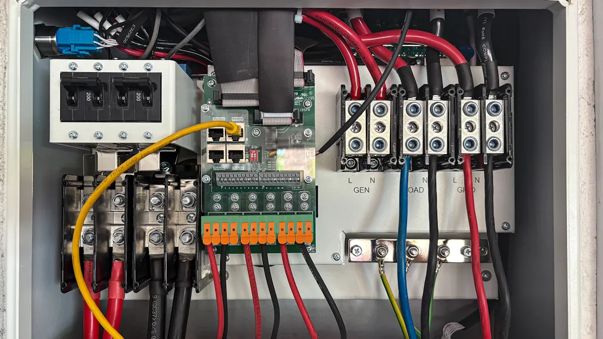
When wiring a single-pole contactor, follow safe practices. Use DIN rail terminal blocks to organize power connections. These blocks keep the L terminals and T terminals secure and neat. Add vertical dividers between L, N, and E terminals to prevent short circuits. Always label wires clearly with tags to avoid confusion during repairs.
Attach bootlace ferrules to wire ends for better connections. Ferrules help wires stay tight and reduce loose connections. Use slotted trunking and expandable braid to protect flexible wires. This setup also makes adjustments easier. Keep power and signal wires apart to stop interference. Never connect the 0V of sensors with the 0V of heavy loads like solenoids. Doing so can cause voltage drops and poor performance.
Tip: Check your wiring against the manufacturer’s instructions to ensure it’s correct.
Common Mistakes When Wiring a Single-Pole Contactor
Wiring mistakes can cause problems or make systems unsafe. A common error is switching the L terminals and T terminals. This mistake stops power flow and may harm devices. Another issue is not tightening terminal screws enough. Loose screws can lead to overheating or sparks.
Using wires that are too thin is also risky. Thin wires can overheat because they can’t handle the current. Forgetting to label wires is another mistake. Without labels, fixing problems becomes harder and more confusing. Lastly, mixing power and signal wires can create electrical noise. This noise can affect how the system works.
Note: Plan your wiring carefully and check every connection to avoid these errors.
Troubleshooting Wiring Issues
Wiring problems can stop a single-pole contactor from working. Fixing these issues needs a step-by-step approach. The table below shows common problems and how to solve them:
|
Issue |
Possible Causes |
Troubleshooting Steps |
|---|---|---|
|
Contactor Chattering |
Low control voltage, worn contacts, overloaded circuit |
Check control voltage, inspect contact surfaces, verify load current |
|
Contactor Remains Closed |
Welded contacts, mechanical failure |
Disconnect power, inspect for damage, replace if necessary |
First, check the control voltage. If it’s too low, the contactor won’t work right. Look at the contact surfaces for damage or wear. Replace damaged contacts to fix the issue. If the contactor stays closed, turn off the power and check inside. Look for stuck contacts or broken parts. Replace anything damaged to restore function.
Tip: Regular checks and maintenance can prevent wiring problems and make your contactor last longer.
Implications of Incorrect Wiring
Electrical Hazards from Miswiring
Wiring a contactor wrong can cause dangerous electrical problems. Miswiring might create short circuits, leading to sparks or fires. Wires connected incorrectly can overheat and melt their coverings. This makes it more likely for someone to get shocked when touching the equipment. Bad connections can also stop the contactor from controlling power safely, putting people and devices at risk.
To stay safe, always check your wiring carefully. Use tools with insulation and wear gloves for protection. Make sure wires are tightly attached to the right terminals.
Tip: Label wires clearly to avoid mistakes during setup or repairs.
Potential Equipment Damage
Wrong wiring doesn’t just cause safety issues—it can break your equipment too. If connections are wrong, three-phase motors might spin backward. This can damage parts or make the motor stop working. Miswiring can also mess up voltage flow, wasting energy and lowering efficiency. Safety features might fail, making equipment more likely to break.
Here are some problems caused by miswiring:
-
Motors spinning backward can harm moving parts.
-
Wasted energy raises electricity bills.
-
Safety risks increase chances of shocks or fires.
Follow the manufacturer’s wiring instructions to protect your equipment. Test the system after setting it up to ensure it works properly.
Preventing Errors When Wiring a Contactor
Avoid wiring mistakes by planning ahead. Before starting, read the contactor’s wiring diagram and learn what each terminal does. Use strong wires that match your system’s current needs. Tighten terminal screws and check for loose wires. Keep power wires away from signal wires to prevent interference.
Regular checks can help you find problems early. Look at the contactor often for wear or damage. Replace old parts to keep the system running well. If you’re unsure about wiring, ask a professional electrician for help.
Note: Taking these steps can save money, time, and prevent equipment damage.
Safety Tips for Working with Contactors
Why Insulation and Proper Tools Matter
Using the right tools and insulation keeps you safe with a contactor. Insulation stops accidental contact with live parts, lowering shock risks. Tools made for electrical work, like insulated pliers and screwdrivers, help during setup or repairs. Always check your tools and safety gear to ensure they are in good shape.
The table below shows important safety tips for tools and insulation:
|
Requirement |
Description |
|---|---|
|
Insulated Tools |
Use tools rated for the voltages near live parts. |
|
Protective Equipment |
Wear gloves when working with parts over 50 volts. |
|
Inspection |
Check rubber gear for damage before and after use. |
|
Testing Circuits |
Test circuits to confirm they are off before starting work. |
Following these steps reduces risks and creates a safer workspace.
Tip: Always use a reliable voltage tester to check circuits before touching them.
Using Manufacturer Guidelines for A1 and A2 Terminals
The A1 and A2 terminals are key parts of a contactor’s control circuit. These terminals connect to the coil, helping the contactor work properly. Wiring for these terminals can differ by model. Always follow the manufacturer’s wiring diagrams to install them correctly.
Key points to remember:
-
The A1 terminal usually connects to the live wire in the circuit.
-
The A2 terminal often connects to the neutral wire.
-
Wrong wiring can damage the coil or cause it to fail.
By following these instructions, you ensure the contactor works well and avoid risks like fires or damage.
Note: Keep the manual nearby during installation for quick guidance.
When to Call a Professional for Help
Some contactor setups are too complex for beginners. Advanced systems with multiple circuits or tricky wiring may need expert skills. Hiring a professional ensures the job is done safely and correctly.
The table below lists areas where experts are helpful:
|
Skill/Knowledge Area |
Description |
|---|---|
|
Technical Drawing Interpretation |
Reading and understanding circuit diagrams. |
|
Installation Principles |
Using proper methods for wiring and control panels. |
|
Safety Regulations |
Knowing risks and taking safety steps during installation. |
|
Fault-Finding Techniques |
Diagnosing and fixing problems with the right tools. |
Getting professional help ensures safety, saves time, and avoids costly errors.
Tip: For difficult installations, always choose safety by consulting an expert.
Knowing what L and T terminals do is important for safe electrical setups. L terminals bring power into the system. T terminals send power to devices that need it. Wiring them correctly helps the contactor work well and avoid dangers.
To stay safe, follow the instructions from the manufacturer. Check the connections often to catch problems early. Wrong wiring can harm equipment or cause safety risks. If the setup is complicated, ask an expert for help to do it right.
Using terminals correctly and wiring carefully keeps your contactor working well and protects people and devices.
FAQ
What do L and T terminals do in an AC contactor?
L terminals bring electricity into the contactor. T terminals send power to the device. They work together to control electricity flow.
Can an AC contactor be used for single-phase and three-phase systems?
Yes, it works for both. Single-phase uses fewer terminals. Three-phase needs more L and T terminals.
How can you find L and T terminals on a contactor?
L terminals are marked as inputs, and T terminals as outputs. Check the wiring diagram to see their exact spots.
What happens if L and T terminals are wired wrong?
Wrong wiring can damage devices, cause hazards, or waste energy. Always follow the wiring diagram to avoid problems.
Do L and T terminals need to be checked often?
Yes, look for loose wires, damage, or wear. Regular checks keep them safe and make the contactor last longer.
The following information may be of interest to you
What do NO and NC on the communication contactor represent
Comprehensive guide for wiring methods of air circuit breakers

