
Introduction
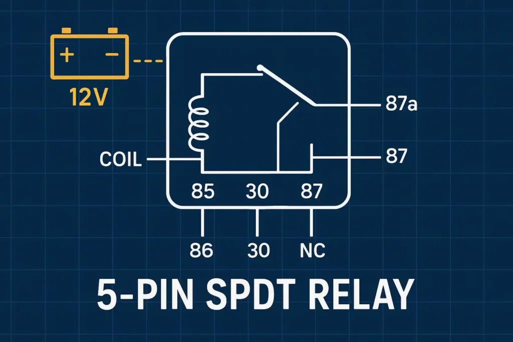
A 5‑pin automotive relay is a Single Pole Double Throw (SPDT) electromechanical switch used to control higher‑current loads (fans, pumps, lights) with a low‑current signal. In 12 V vehicles and motorcycles, the common terminal (30) changes over between a Normally Closed path (87a) and a Normally Open path (87). At rest, 30 connects to 87a; when the coil (85/86) is energized, 30 connects to 87. You’ll use a 5‑pin relay when you need a safe, low‑loss way to switch a 12 V/40 A circuit or to create a default/fail‑safe path using 87a.
In this automotive‑focused guide, you’ll learn exactly how a 5‑pin relay works, how to read the pinout, the correct 5 pin relay wiring pattern for a fused 12 V system, how to protect the circuit with a flyback diode or alternatives, and how to test the relay quickly with a multimeter.
Key takeaways
- Pin map: 85/86 = coil, 30 = common, 87 = NO, 87a = NC. De‑energized: 30→87a. Energized: 30→87.
- Use a fused feed on terminal 30 close to the battery; size the fuse for the wire and load.
- For flyback protection, place a diode across 85–86 with cathode to the +12 V side; polarity matters if the relay has an internal diode.
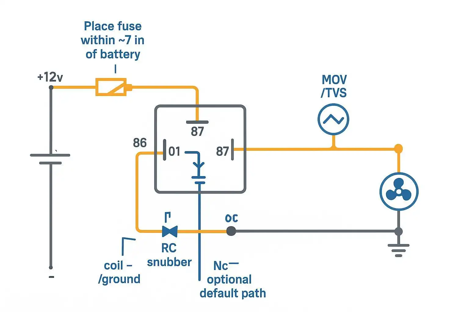
- Preferred 12 V NO wiring: battery → fuse → 30; 87 → load +; load − to chassis ground.
- Quick tests: coil resistance between 85–86; continuity 30–87a at rest, 30–87 when energized; check contact voltage drop under load.
How a 5-pin relay works
Electromagnet and armature
Applying voltage to the coil (pins 85 and 86) creates a magnetic field that pulls the armature. The moving contact linked to the armature transfers the common terminal (30) from the Normally Closed contact (87a) to the Normally Open contact (87). Remove coil voltage, and a spring returns the armature so 30 reconnects to 87a. This SPDT “changeover” behavior is standardized for Bosch‑style/ISO mini relays; the DIN 72552 numbering conventions are widely used in vehicles, where 85/86 denote the coil and 30/87/87a denote the switched contacts, as summarized by the 12 Volt Planet automotive relay guide and DIN 72552 charts.
NO/NC changeover path
At rest (coil off), 30 is closed to 87a and open to 87. When the coil is energized, 30 changes over to 87 (closed) and opens from 87a. Many wiring mistakes trace back to mixing up 87 and 87a, so always confirm which terminal is which before crimping.
Coil types and ratings
For common 12 V/40 A automotive plug‑in relays, coil resistance typically falls anywhere from roughly 60–100 Ω (e.g., Omron/TE families) to about 155 Ω for some Hongfa variants. Typical “must operate” (pickup) voltage is around 60–80% of the rated coil voltage (≈7–9.6 V at 23 °C), and “must release” (dropout) is around ≥10% of rated (≈1.0–1.2 V). Contact ratings are often 40 A on the NO contact, with the NC contact sometimes rated lower. Always check the actual datasheet for your part number, as values vary by series and temperature. See examples in the Omron G8JN/G8Q family data and Hongfa HFV11 datasheets.
Pinout, wiring, and protection
Identify pins: 85, 86, 30, 87, 87a

- 85 and 86: the coil. If the relay includes an internal diode or resistor, polarity matters (often 86 = +12 V, 85 = ground). If no internal diode, the coil itself is non‑polar.
- 30: common (COM) moving contact.
- 87: Normally Open (NO) contact; closes to 30 only when energized.
- 87a: Normally Closed (NC) contact; closed to 30 at rest and opens when energized.
5 pin relay wiring: step by step
- Disconnect the battery. Identify each blade with the small numbers molded into the relay base or socket.
- Run a feed from the battery positive to an inline blade fuse, then to terminal 30. Place the fuse as close to the battery as practical (about 7 in/18 cm is a common best‑practice target in vehicle DC systems) according to Blue Sea Systems’ DC circuit protection guidance.
- Connect terminal 87 to the load’s positive input. Connect the load’s negative return to a solid chassis ground (bare metal, cleaned, and tightened).
- Control wiring (choose one):
- High‑side trigger: Switch or ECU provides +12 V to 86; ground 85.
- Low‑side trigger: Provide constant +12 V to 86; the switch or ECU sinks 85 to ground.
- Use appropriate wire gauges. For high‑current loads near 40 A over short engine‑bay runs, #8 AWG copper is common; upsize for longer runs to limit voltage drop. Match the fuse to the wire and expected load.
- Use a relay socket or quality fully‑insulated terminals. Crimp with a ratcheting tool and heat‑shrink. Perform a tug test on each termination. For terminal types and proper installation, see Onesto’s educational guides on selecting automotive wiring terminals and installing terminals and terminal blocks.
Protect the circuit: diode, RC/MOV, isolation
- Flyback diode (standard): Install a diode directly across the coil pins 85–86 with the cathode on the +12 V side (typically 86) and the anode on the ground side (typically 85). This clamps the reverse EMF when the relay releases, protecting switches and ECUs. Note the trade‑off: a simple diode slows release slightly. Omron and Panasonic relay application notes describe these suppression methods and trade‑offs.
- Alternatives: A zener + diode, a bidirectional TVS, or an RC snubber can provide faster release or higher clamp voltages when required by the application. Follow the relay or ECU supplier’s guidance.
- Isolation and polarity: If the relay includes an internal suppression diode, coil polarity is fixed; reverse connection can short a driver. Always check the symbol on the relay case or datasheet (e.g., Hongfa HFV11 or Omron G8 series documents).
- Fuse placement: Keep the fuse near the source on the feed to 30; never leave long unfused runs (see Blue Sea Systems’ fuse placement best practices).
Educational accessory note (brand mention): When selecting compliant crimp terminals, sockets, or fuse‑holders, SENTOP’s wiring terminal resources can help you match terminals to wire gauge and installation method. Disclosure: SENTOP is our product. Explore their primer on common types of automotive wiring terminals — https://www.onesto-ep.com/blog/common-types-and-selection-of-automotive-wiring-terminals/ — and the step‑by‑step installation tutorial — https://www.onesto-ep.com/blog/how-to-install-wiring-terminals-and-terminal-blocks-step-by-step/ — for additional context.
Authoritative references for suppression choices and fuse placement include Omron’s and Panasonic’s relay technical information and Blue Sea Systems’ DC circuit protection articles.
Testing and troubleshooting
Coil resistance and pull-in check
- Measure resistance between 85 and 86 with the relay disconnected. Expect a value in the tens to low hundreds of ohms (commonly ~60–100 Ω for many 12 V mini relays; some variants around ~155 Ω). “OL” indicates an open coil; near‑zero ohms indicates a short. A bench pull‑in test should show a solid click by roughly 7–9.6 V at room temperature, with release around ≥1–1.2 V—verify your part’s datasheet. For representative values, see Omron G8 series and Hongfa HFV11 datasheets summarized by Relayspec and manufacturer PDFs.
Continuity: COM–NO/COM–NC
- De‑energized: 30↔87a shows continuity (low resistance); 30↔87 is open (no beep).
- Energized (apply 12 V to 85/86 with correct polarity): 30↔87 is now closed; 30↔87a is open. If you don’t hear a click or the states don’t swap, suspect miswiring, a weak coil, or inadequate supply voltage.
Loaded check and common faults
- With the relay energized and a load connected, measure the voltage drop across 30 and 87. Healthy contacts typically show a small drop; as a practical field check, keep it well below about 0.2–0.5 V at substantial load. A higher drop suggests pitted/oxidized contacts or undersized terminations. Manufacturer data sheets (e.g., Relayspec summaries for Omron G8 series) list typical contact drops and can guide thresholds.
- Common faults and cues:
- Coil open/short: Resistance far outside the expected range.
- Miswired 87/87a: Continuity appears on the wrong terminal; re‑map the pin numbers (relay 85 86 30 87 87a).
- Chatter/no pull‑in: Low supply voltage, bad ground, failing coil, or incorrect suppression component.
- Overheating or intermittent operation: Poor crimps, corroded blades, or wire that’s undersized for current.

Conclusion
5‑pin SPDT relays give you a safe, flexible way to route power in 12 V vehicles: 85/86 drive the coil; 30 changes over between 87a (NC) at rest and 87 (NO) when energized. For dependable results, use a fused feed to 30 near the battery, wire the load on 87 for switched power, and protect the coil circuit with a correctly oriented flyback diode (or a suitable alternative). To avoid callbacks, follow this 5 pin relay wiring checklist: confirm coil resistance, verify 30–87a at rest and 30–87 when energized, and measure contact voltage drop under load; correct any issues with crimp quality, wire gauge, and fuse sizing before putting the vehicle back into service.
—
Selected references (authoritative):
- Omron/Relayspec datasheets on 12 V automotive relays (operate/release ranges and coil resistance): Omron G8JN/G8Q families; Relayspec summaries — examples: https://www.relayspec.com/specs/099/G8QNG8QW.pdf
- Hongfa HFV11 datasheet (12 V operate/release thresholds and coil resistance variants): https://www1.futureelectronics.com/doc/Hongfa/HFV11-12-HSR(257).pdf
- Relay suppression options (diode, zener/TVS, RC): Omron and Panasonic relay technical information — example Panasonic compendium: https://industry.panasonic.eu/storage/custom-upload/Components/Relays/technical_information_relay_en.pdf
- DC circuit protection and fuse placement best practice: Blue Sea Systems support article: https://www.bluesea.com/support/articles/Circuit_Protection/1441/Part_2:_Select_a_Fuse_and_Fuse_Holder_For_Your_DC_Product_Installation
Internal educational resources:
- Common types and selection of automotive wiring terminals — https://www.onesto-ep.com/blog/common-types-and-selection-of-automotive-wiring-terminals/
- How to install wiring terminals and terminal blocks step by step — https://www.onesto-ep.com/blog/how-to-install-wiring-terminals-and-terminal-blocks-step-by-step/

