
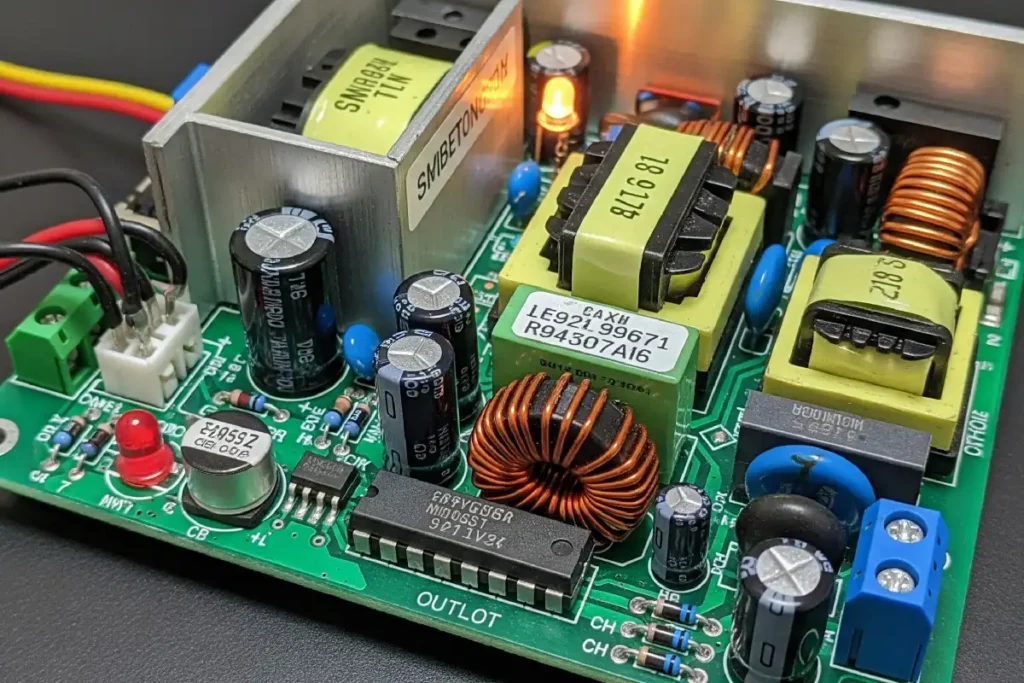
Switching power supply components include the controller IC, power transistors, diodes, transformer, inductors, and filter capacitors. Each switching power supply component plays a specific role. The controller IC sets the timing, power transistors switch the current on and off, diodes ensure electricity flows in the correct direction, transformers adjust the voltage, inductors store energy for later use, and capacitors smooth out the output. Understanding these switching power supply components helps engineers troubleshoot issues more quickly and create more efficient designs.
| Aspect | Impact on Troubleshooting and Design Success |
|---|---|
| Component Functions | Makes things work better and last longer, with less guessing. |
| Efficiency Management | Stops things from getting too hot and helps them last longer. |
Key Takeaways
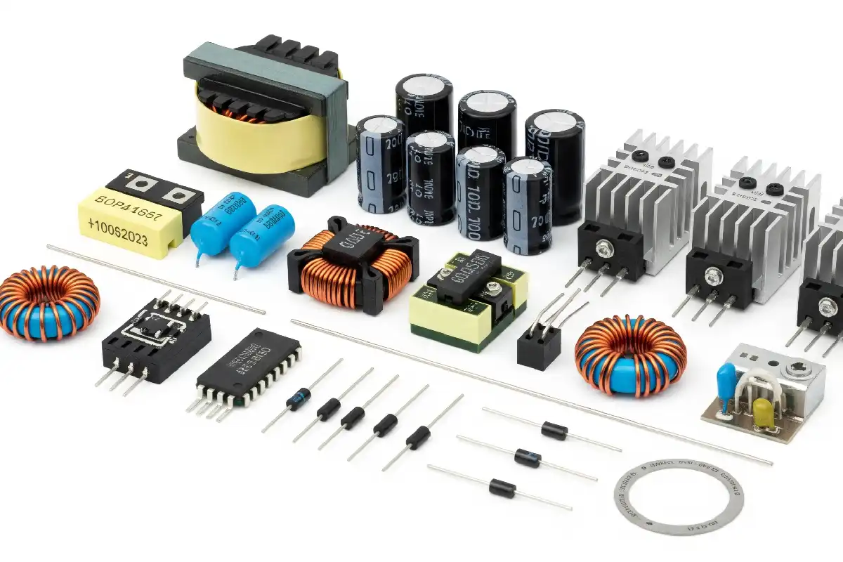
- Switching power supplies have parts like controllers, transistors, transformers, diodes, inductors, and capacitors. These parts help change and control electricity in a smart way.
- The input stage gets the power ready and keeps it safe. It makes sure devices get steady and safe electricity. It also helps lower heat and noise.
- Power conversion parts turn electricity on and off very fast. They change the voltage and store energy. This helps keep power steady and saves energy.
- The output stage makes the power smooth before it goes to devices. It keeps the voltage steady even if the load changes.
- Control and protection circuits help keep the power supply safe. They manage voltage and stop damage. They also help the power supply work better for a long time.
Switching Power Supply Components
Switching power supply components team up to change electrical energy. They do this in a way that saves energy and works well. Each part has its own job. Together, they make sure electronic devices get steady power. The main groups are the input stage, power conversion, output stage, and control and protection circuits.
Input Stage
The input stage gets the power ready for the circuit. It starts with a fuse and a Metal Oxide Varistor (MOV). These protect against too much voltage. The AC input goes through a bridge rectifier. This changes AC into DC. A filter capacitor makes the DC voltage smooth and steady. This step is important for the whole power supply. A good input stage helps stop heat, keeps the output steady, and protects from power surges.
Tip: A strong input stage means fewer problems later. Devices like smartphones and laptops need this for safe charging.
| Feature | Benefit | Application |
|---|---|---|
| High Efficiency | Saves energy and cuts down on heat and power use | Used in electronics like smartphones and laptops |
| Compact Design | Smaller and lighter because of high-frequency work | Used in portable devices and industrial systems |
| Wide Input Voltage Range | Works well even if power changes or is unstable | Used in renewable energy and industrial automation |
| Low Heat Generation | Less heat means parts last longer | Used in medical devices and industrial controllers |
| Voltage Regulation | Keeps output steady for sensitive electronics | Used in telecommunications and cars |
Power Conversion
The power conversion stage is the main part of the switching power supply. Power transistors act as fast switches. They turn on and off quickly to control current. The transformer changes the voltage and keeps input and output apart. Inductors store energy and help control current. Diodes make sure current goes the right way and protect against voltage spikes.
- Controller IC: Sets the timing and controls the switches.
- Power Transistors: Turn current on and off to control energy.
- Transformer: Changes voltage and keeps input and output separate.
- Inductors: Store energy and help smooth current changes.
- Diodes: Guide current and protect against spikes.
- Filter Capacitors: Make voltage smooth and cut down noise.
New Gallium Nitride (GaN) transistors switch faster and work better. Modern designs can be more than 96% efficient. This means less wasted energy and smaller, cooler devices.
| Component/Aspect | Role/Interaction | Evidence of Effectiveness |
|---|---|---|
| Transistor (Switch) | Works as a switch, turning fully on and off | Cuts power loss and helps reach over 90% efficiency in buck converters |
| Inductor and Diode | Handle energy and keep output voltage steady with low ripple | Output voltage is controlled by duty cycle |
| Duty Cycle Control | Balances on and off times to control output voltage | Output voltage matches duty cycle; for example, 27.5% duty cycle gives 3.3V output from 12V input |
| Advanced Topologies | Use more switches and modes for better results | Can reach up to 98% efficiency and work with many input voltages and high power density |
Output Stage
The output stage gives steady voltage and current to the load. It uses output rectifiers and filter capacitors to smooth the voltage. This removes any leftover ripple from switching. Inductors help keep the current steady. The output stage must react fast to changes in load. It keeps the voltage in a tight range.
- The output stage checks the output and adjusts as needed.
- An error amplifier helps keep the output steady, even if things change.
- Switching regulators use feedback to adjust pulse width and keep the output right.
| Parameter | Description | Example / Data Point |
|---|---|---|
| Dropout Voltage | The lowest voltage where the regulator can keep output steady | 172 mV at 2 A load (ADM7172) |
| Load Regulation | Keeps output voltage steady when load changes | ∆VOUT/∆IOUT shown in Figure 6 |
| Line Regulation | Keeps output voltage steady when input changes | Output voltage vs. input voltage shown in Figure 7 |
| Output Noise Voltage | Measures noise in the output, affects signals | 5 μV rms to 100 μV rms |
| Efficiency | Shows how much input power becomes output power, affected by dropout and ground current | 3.3 V LDO efficiency max 91.7% at 3.6 V input |
Control and Protection
Control and protection circuits keep the switching power supply safe and steady. The controller IC manages switch timing. It makes sure the output stays in the right range. Feedback loops check the output and adjust switching. Protection features like over-voltage, over-current, and short-circuit protection stop damage.
- Over-voltage protection shuts off output if voltage is too high.
- Over-current protection limits current to stop overheating.
- Short-circuit protection lowers output current during faults.
- Advanced EMI filtering and Power Factor Correction (PFC) help efficiency and reliability.
Switching power supply components must work together well. Every part, from the controller IC to the filter capacitors, helps make the power supply efficient, reliable, and safe for modern electronics.
Input Stage
Input Filter
The input filter is the first part that protects the switching power supply. It stops unwanted noise and makes the incoming current smoother. Engineers use LC low-pass filters to cut down on electromagnetic interference, or EMI. This is most important at the switching frequency and its harmonics. These filters help the power supply follow rules like CISPR 22 and EN55022. These rules set tough limits for EMI that is conducted and radiated.
Input filters are best at blocking conducted noise from 150 kHz to 30 MHz. Radiated EMI, from 30 MHz to 1 GHz, is harder to stop. It needs careful PCB layout and other design steps. Input filters are very important, but they are not the only way to meet all EMI rules.
- The input stage filters out rough currents from switching devices. This lowers voltage ripple and conducted noise.
- Using symmetrical capacitor layouts and small loops makes magnetic fields that cancel each other. This helps lower radiated EMI.
- EMI filters at the input help meet noise rules.
- Good ground planes and better packaging lower EMI by cutting down spikes.
- The input filter smooths out currents and keeps noise from spreading.
Rectifier
The rectifier changes AC power from the wall into DC power for the circuit. Most switching power supplies use a bridge rectifier. This type uses the whole AC cycle and gives a steady, efficient DC output.
| Rectifier Type | Efficiency Level | Output Characteristics | Typical Applications |
|---|---|---|---|
| Half-Wave Rectifier | Low | Pulsating DC | Basic power supplies |
| Full-Wave Rectifier | Moderate | Smoother DC | General electronics |
| Bridge Rectifier | High | Higher, smoother DC output | High-performance power supplies |
Switching power supplies can be more than 95% efficient. Bridge rectifiers help by giving steady DC output with less energy loss.
Power Factor Correction
Power factor correction, or PFC, helps the power supply use electricity better. It shapes the input current to match the input voltage. This cuts down wasted energy and lowers interference. Passive PFC uses filters and gets a power factor of about 0.70 to 0.75. Active PFC uses switching converters, like boost converters, to get close to 0.99. This means almost all the power from the wall is used well.
Active PFC also moves unwanted harmonics to higher frequencies. This makes them easier to filter out. It makes power quality and efficiency better, but adds some cost and complexity. Most modern switching power supplies use active PFC to meet strict energy and noise rules.
Power Conversion
Switching Transistor
Switching transistors work as the main switches in power conversion. They turn on and off very fast to control electricity flow. Engineers pick different transistors for speed or efficiency. NPN transistors are good for high-frequency power supplies because they switch fast. PNP transistors switch slower and are better for low-frequency or audio circuits. The table below shows how they compare:
| Transistor Type | Switching Speed Characteristics | Efficiency Characteristics |
|---|---|---|
| NPN | Fast switching speeds suitable for high-frequency power supplies | Higher efficiency in some high-frequency switching designs |
| PNP | Slower switching speeds, used in low frequency and audio applications | Effective in lower power consumption scenarios, improving energy efficiency |
NPN transistors work well in high-frequency designs but can get hot. PNP transistors help save energy in low-power circuits.
Transformer
The transformer in a switching power supply changes voltage levels. It also keeps input and output separate for safety. It uses high-frequency signals, so it can be smaller than old transformers. The transformer loses some energy when it works. Losses come from wire resistance, eddy currents, and magnetic effects. The table below explains these loss types:
| Loss Type | Description |
|---|---|
| Resistive Loss | Power loss due to resistance in copper windings (I²R losses), increased by skin effect at high frequencies. |
| Eddy Current Loss | Currents induced in the core by changing magnetic fields cause heating; minimized by laminated iron sheets. |
| Hysteresis Loss | Energy lost due to magnetic domain realignment in the core material, producing heat during polarity changes. |
| Flux Loss | Loss from magnetic flux lines not passing through the core, usually small if transformer is well designed. |
Transformers in switching power supplies give galvanic isolation. This protects people from electric shock. They also step voltage up or down as needed. Most transformer losses are about 2% of total energy loss. Modern designs use special materials to lower these losses and make them work better.
Topologies
Engineers use different circuit topologies for each job. The most common ones are buck, boost, flyback, and forward converters. Each has its own features and efficiency range. The table below compares them:
| Topology | Efficiency Range | Key Features | Typical Applications |
|---|---|---|---|
| Buck | 85% - 95% | Step-down voltage, simple, continuous input current | Microprocessor power supplies, battery-powered devices, industrial electronics |
| Boost | High | Step-up voltage, used when output > input voltage | Battery-powered devices, renewable energy systems, power factor correction circuits |
| Flyback | 80% - 90% | Galvanic isolation, multiple outputs | Medical equipment, telecommunications, consumer electronics |
| Forward | 85% - 95% | Galvanic isolation, continuous output current | Industrial equipment, telecommunications, military/aerospace |
Buck and boost converters are best for simple, non-isolated designs. Flyback and forward converters give isolation and can power many outputs. Engineers pick the best topology based on voltage, isolation, and efficiency needs.
Output Stage
Output Rectifier
The output rectifier turns AC from the transformer into DC for the load. Full-wave and bridge rectifiers use both parts of the AC cycle. This makes the output smoother and helps efficiency. These rectifiers make ripple at twice the AC frequency. This makes it easier to filter out voltage changes. In switching power supply components, the ripple frequency is much higher. Smaller capacitors can be used for filtering. The type of rectifier changes the output voltage ripple and efficiency. Full-wave designs give more DC output and less ripple. This helps sensitive devices work better.
Output Filter
The output filter takes away noise and ripple from the DC voltage. It does this before the voltage goes to the load. Engineers use LC filters with inductors and capacitors. These block high-frequency noise. Output capacitors fight against the power supply’s output impedance. This lowers noise levels. Adding series inductors helps block high-frequency signals. Ferrite beads also help filter out switching spikes. Good PCB layout and shielding make the filter work better. Using low-noise linear regulators after filtering can lower ripple even more. This makes the output cleaner for audio circuits and sensors.
Output filters help keep voltage steady when the load changes fast. Wide band output stages and four-wire sensing keep voltage accurate at the load. This works even when current changes quickly. Some power supplies, like the Keithley Series 2300, recover from big load changes. They do not drop below important voltage levels.
Output Capacitors
Output capacitors store energy and help smooth DC output. Polymer capacitors use solid polymers. These do not leak or dry out. They have very low ESR and are great for filtering and lowering ripple. Ceramic capacitors are small and have low ESR. Their capacitance can change with temperature and voltage. Aluminum electrolytic capacitors have high capacitance but higher ESR. They can wear out over time. Tantalum capacitors are reliable and small. They do not work as well at high frequencies. Putting capacitors in parallel gives more capacitance and lower ESR. This makes filtering and stability better.
| Capacitor Type | Advantages | Disadvantages | Impact on Performance |
|---|---|---|---|
| Ceramic (MLCC) | Low ESR, small size | Piezoelectric effect, changes in capacitance | Cuts ripple, good for high frequency |
| Aluminum Electrolytic | High capacitance, low price | High ESR, big size, wears out | More ripple, less efficient |
| Tantalum | Reliable, small | Expensive, not good at high frequency | Stable, not best for switching |
| Polymer | Low ESR, high capacitance | Expensive, voltage limits | Great filtering, steady output |
Control and Protection
Controller IC
The controller IC is like the brain of the power supply. It controls when the switching transistors turn on and off. This chip uses a feedback loop to keep voltage steady. Inside, it has voltage references, comparators, and amplifiers. These help the IC change how long the switches stay on. Fast switching, from 50 kHz to 1 MHz, lets engineers use smaller inductors and capacitors. This makes the power supply smaller and more efficient. Some controller ICs have special packaging, like Silicon on Sapphire. This helps them work in hot or tough places. The table below lists main functions and how they help efficiency:
| Key Function / Feature | Description | Impact on Efficiency |
|---|---|---|
| Regulation of output voltage | Adjusts duty cycle to keep voltage stable | Reduces power loss, improves efficiency |
| Analog building blocks | Uses voltage references and amplifiers for control | Increases reliability and efficiency |
| High-frequency switching | Enables smaller passive components | Boosts power density, raises efficiency up to 95% |
| Integration and packaging | Advanced designs for high temperature and fewer parts | Lowers losses, improves reliability |
| Demonstrated performance | Efficient operation with minimal components | Enables compact, high-performance designs |
Feedback Loop
The feedback loop helps keep the output voltage correct. It checks the voltage and compares it to a set value. If the voltage changes, the loop quickly sends a signal to fix it. This happens in just a few microseconds. Engineers use compensation networks to tune the feedback loop. These networks set how fast and stable the loop is. A higher bandwidth means the power supply reacts faster. A bigger phase margin makes the power supply more stable and less likely to shake. The table below explains important feedback loop details:
| Aspect | Explanation | Typical Values / Notes |
|---|---|---|
| Feedback Loop Function | Monitors and corrects output voltage | Keeps voltage close to desired value |
| Control Loop Tuning | Adjusts gain and phase for stability and speed | Uses compensation networks |
| Crossover Frequency | Sets response speed | 7 kHz to over 60 kHz |
| Phase Margin | Measures stability | Above 45°, often 59° to 92° |
| Response Time | Speed of voltage correction | Microseconds to tens of microseconds |
| Design Trade-offs | Balances speed, stability, and noise | Careful tuning needed |
Protection Circuits
Protection circuits keep the power supply and devices safe from harm. They watch for problems like too much current, high voltage, or heat. When something goes wrong, these circuits act fast to stop damage. Common protection features include:
- Overcurrent protection: Fuses, breakers, and switches stop big current surges.
- Overvoltage protection: TVS diodes and MOVs send extra voltage away from parts.
- Thermal protection: Sensors and thermal fuses watch heat and shut off if it gets too hot.
- Overload protection: Slow-blow breakers and relays guard against long high current.
These features work with the control circuit. They help the power supply keep steady output and avoid problems. Engineers adjust compensation networks for the best speed and stability. Adding capacitors or resistors can make the phase margin better and lower voltage swings. All these parts work together to keep the power supply safe and working well.
Switching power supply components are all important. Transformers change voltage to the right level. Rectifiers turn AC into DC for steady power. Voltage regulators keep the voltage from changing too much. Protection devices stop damage and help things last longer.
| Component / Function | Role and Importance |
|---|---|
| Transformers | Change voltage so power is safe. |
| Rectifiers | Make AC into DC for steady power. |
| Voltage Regulators | Keep voltage the same. |
| UPS | Give backup power if the main power stops. |
| Protection Devices | Stop damage from power surges. |
When engineers know these parts well, they can make safer and better systems. If you want to learn more, check out these resources:
| Title | Focus Area / Description |
|---|---|
| Switching power supply topology review | Shows different ways to build power supplies |
| Practical considerations in current-mode power supplies | Gives tips for design and fixing problems |
| Closing the feedback loop | Explains how to keep voltage steady and stable |
When you understand what each part does, you can pick the best ones and make sure your device always gets good power.
FAQ
What is the main job of a switching power supply?
A switching power supply changes electricity from one type to another. It gives steady voltage and current to devices. It does this by turning power on and off very fast.
Why do engineers use transformers in switching power supplies?
Transformers change voltage levels and keep input and output apart. This helps protect people from electric shock. Transformers also make power supplies safer and more useful.
How does a feedback loop help in a switching power supply?
The feedback loop checks the output voltage. It tells the controller to change switching if voltage moves. This keeps the output steady for the device.
What happens if a power supply does not have protection circuits?
Devices can break from too much current, high voltage, or heat. Protection circuits stop these problems. They help power supplies last longer and keep devices safe.
Which capacitor type works best for filtering high-frequency noise?
| Capacitor Type | Best Use |
|---|---|
| Ceramic (MLCC) | High-frequency filtering |
Ceramic capacitors are best for filtering high-frequency noise. They have low ESR and react quickly to voltage changes.
See also
What Happens When a Switching Power Supply Converts AC Power to DC
Why does your air conditioning circuit breaker always trip?
How to Choose the Right Switching Power Supply for Your Project
How to Minimize Electromagnetic Interference in Solar Inverter Systems
What size conversion switch is needed for a generator

